Feniex 4200-DL Manuel utilisateur
4200 DL Instruction Manual
1.800.615.8350 / feniex.com
Feniex Product Copyrights This price List and the mentioned Feniex products include or describe copyrighted Feniex material. Laws in the
United States and other countries preserve for Feniex Industries and its licensors certain exclusive rights for copyrighted material, including the
exclusive right to copy, reproduce in any form, distribute and make derivative works of the copyrighted material. Accordingly, any copyrighted
material of Feniex and its licensors contained herein or in the Feniex products described in this Price List may not be copied, reproduced,
distributed, merged or modied,transmitted, transcribed, stored in retrieval system or translated into any language or computer language, in any
form or by any means, without prior written permission of Feniex Industries, Inc.. Feniex and the stylized Feniex logo are registered in the U.S.
Patent & Trademark Oce.
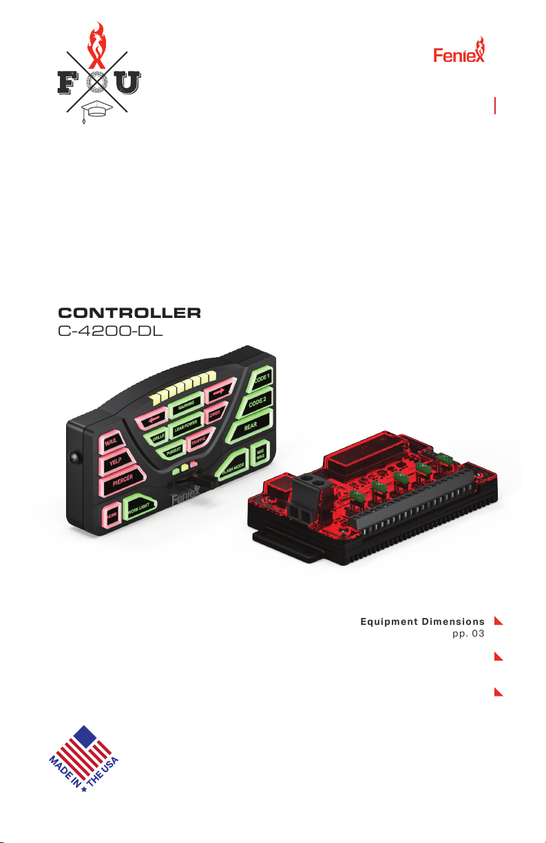
4200 DL
CONTROLLER
C-4200-DL
Equipment Dimensions
pp. 03
Specifications
pp.03
Wiring Diagram
pp.04
Feniex University
feniexuniversity.com
4200 DL

If the product needs to be returned for repair
or replacement, call our customer support line
to receive a return merchandise authorization
number.
Operational times are from 10 a.m. to 5 p.m.
central time, Monday through Friday. Please
do not send in product without contacting
support rst for a RMA number.
Service After Expiration
Feniex Industries will still provide service for
all products after expiration of the warranty.
For any issues, call the customer support
line. In some instances it may be necessary
for the product to be shipped, freight prepaid
and insured for loss or damage to Feniex
headquarters.
Copyright
This instruction manual and the Feniex
products described in this instruction manual
may include or describe copyrighted Feniex
material. Laws in the United States and other
countries preserve for Feniex Industries
and its licensors certain exclusive rights for
copyrighted material, including the exclusive
right to copy, reproduce in any form, distribute
and make derivative works of the copyrighted
material. Accordingly, any copyrighted
material of Feniex and its licensors contained
herein or in the Feniex products described in
this instruction manual may not be copied,
reproduced, distributed, merged or modied
in any manner without the express written
permission of Feniex Industries, Inc.
Feniex Product Copyrights
The products described in this document
are the property of Feniex Industries, Inc. It is
furnished by express license agreement only
and may be used only in accordance with the
terms of such an agreement. Products and
documentation are copyrighted materials.
Making unauthorized copies is prohibited by
law. No part of the product or documentation
may be reproduced, transmitted, transcribed,
stored in retrieval system or translated into any
language or computer language, in any form or
by any means, without prior permission from
Feniex Industries, Inc.
Safety Regulations
The following provides all the information
necessary to safely operate the previously
listed products of Feniex Industries, Inc. Please
read this manual thoroughly before installing or
operating your new product in order to prevent
any damage or injury. Failure to follow the
listed instructions in this manual may result in
damage to your products or personal injury.
• Proper installation of this product requires
good knowledge of automotive systems,
electronics and procedures.
• Please guarantee all vital components
of the vehicle are not in danger of being
damaged by drilling holes necessary for
installation. Check all sides of the mounting
surface before drilling any holes into the
vehicle.
• Do not install this product in any way
that interferes with the deployment of
the air bag. Doing so may damage the
eectiveness of the air bag and can lead
to serious personal and vehicle injury. The
installer will assume full responsibility of
proper installation of the new unit.
• Please clean the mounting surface before
installation of the unit when using tape,
brackets, magnet, Velcro or suction cups.
• The product's ground wire must be
connected directly to the Negative (-)
battery post for eective use of the unit.
Please follow all wiring guidelines provided
to guarantee long lifespan and productivity.
Failing to follow these instructions may
result in damage to the product.
Warranty
Feniex Industries, Inc. warranties to the original
purchaser that all our products shall be free
from defects in material and workmanship.
Feniex Industries' speakers, sirens, rocker
panels, AM600 Beacons, Torch Lights, AI
lightbars, AI Cubes, AM900 Work Lights, 8.5”
Dome Lights, ashlights, Remote Spot Lights
and controllers are warrantied for 2 years from
the manufacturing date. In addition, all other
products are warrantied for 5 years from the
manufacturing date.
If a warranty problem occurs, please contact
customer support at 1.800.615.8350 or visit
the web site at www.Feniex.com.
Warning! Utilizing non-factory screws and mounting
brackets may result in loss of warranty coverage.
Feniex Industries, Inc.
1.800.615.8350 / feniex.com
2
SAFETY REGULATIONS & WARRANTY

Feniex Industries, Inc.
1.800.615.8350 / feniex.com
3
EQUIPMENT DIMENSIONS
6.9"
4.6"
1.0" 4.4"
6.3"
3.3"
14200 Data Link Relay
1
1
2
4200 Controller
U-Shaped Bracket
Ethernet Cable
COMPONENTS
1USB Cable
2
4
Screws
Button Legends
4200 Controller
4200 Data Link Relay
Ethernet Cable
USB Cable
Button
Legends
U-Shaped Bracket
Feniex Industries, Inc.
1.800.615.8350 / feniex.com
4
■Important: Provide 12V+ to the "Ignition Input" (Input H)
SYSTEM SPECS
Input Power 11-16 VDC
Maximum Input Current
Maximum Output
Standby Current
60 Amps
60 Amps
100mA +/-
External Fuse 125% of Circuit Load
Programmable Inputs
System Inputs
Relays
2 Ground, 3 Positive
Ignition, Day, Night
Solid State, Built-in
Switch Type Latching, Momentary, Timed
Buttons
Warranty
Rubberized, Backlit, 2 Colors
2 years
WIG-WAG FLASH PATTERNS
Single Fash (Slow)
Single Flash (Fast)
Single Flash (Combo)
Highbeam Override
Wig Wag Disable

Feniex Industries, Inc.
1.800.615.8350 / feniex.com
5
1. Mount the U-Shaped Bracket in
the desired location using 2 self-
tapping screws. If you wish to use
machine screws, simply drill out the
required hole size based on the size
of screw choice.
Important! Make sure not to dam-
age any vital parts of the vehicle or
mounting surface. Do not mount
anywhere that interferes with the
vehicle air bag.
2. Re-attach the control panel head
to the U-Shaped bracket utilizing
the factory provided screws.
3. Connect the RJ45 cable to the
RJ45 port located on the rear of the
controller.
MOUNTING INSTRUCTIONS
4200 Controller
U-Shaped Bracket

Feniex Industries, Inc.
1.800.615.8350 / feniex.com
6
CONFIGURATION RECORD
Use this page to record the products connected to each outlet to assist
when programming the control head with the provided software
package.
Outputs: Buttons: (1 - 18, P1 - P3)
1 1
2 2
3 3
4 4
5 5
6 6
7 7
8 8
9 9
10 10
11 11
12 12
13 13
14 14
15 15
16 16
17 17
18 18
19 P1
20 P2
P3
Input/Polarity:
A (-) F- Night (+)
B (-) G- Day (+)
C (+) H- Ignition (+)
D (+)
E (+)

Feniex Industries, Inc.
1.800.615.8350 / feniex.com
7
FUSION-S 49" AND 60" LIGHT
BARS AND DATA LINK
The included adapter and jumpers are to allow for Fusion-S
49" and 60" to be plugged into any one of the data link out-
puts on the 4200 Relay.
To connect and use this adapter for the Fusion-S 49" and
60" lightbars follow these steps:
1. Remove and use this adapter for the Fusion-S 49" and
60" to be plugged into any one of the data link outputs of
the 4200 Relay.
2. Pull the top plastic lens o
3. Add one of the three supplied jumpers to position one as
shown in the image below. The remainig jumpers are includ-
ed in case one is lost. Only one is need for this.
4. Place the cover back on and secure with hardwarethat
was removed in step one.
5. Connect the white and green wires into the screws termi-
naladapter included with the 4200.
6. Plug in the RJ-45 adapter to any one of the Data Link out-
puts on the 4200 Relay.
7. Program the crontoller with any one of the Data Link
Fusion-S lightbar 15 inputs.
Note: This adapter will only work for bars shipped after 11/15/2021

Feniex Industries, Inc.
1.800.615.8350 / feniex.com
8
1. Remove the top of the lightbar by removing the 8 screws
on the top cover.
2. Pull the top plastic lens o.
3. Add one of the three supplied jumpers to position one as
shown in the image below. The remianig jumpers are includ-
ed in case one is lost. Only one is needed for this.
4. Place the cover back on and secure with hardware that
was removed in step one.
5. Connect the white and green wires into the screw termi-
nals of the RS-45 into the screw terminal adapter included
with the 4200.
6. Plug in the RJ-45 adapter to any one of the Data Link
outputs on the 4200 Relay. See the image below for wiring
to adapter.
RJ-45 Terminal Adapter to Green/White Wires from Fusion-
S Product Wiring:
A: White
B: Green
FUSION-S 49" AND 60" LIGHT
BARS AND DATA LINK

Feniex Industries, Inc.
1.800.615.8350 / feniex.com
9
PROGRAMMING SOFTWARE
To program the Feniex 4200
Controller, rst visit feniex.com to
download the software.
Help
For assistance on how to use the
software, please click the help
button located on the top bar in
the software interface. You will
nd informative videos on how
to program every function of the
4200 software system.
1. Connect the provided USB wire
to the controller, and connect the
other end of the USB port to the
computer.
2. When the controller is plugged
in, the red box reading "Device
Disconnected" will change from
Red to Green will read: "Device
connected."
Ports 1-20 can be activated by:
• Button
• Input
• Slide Switch (p1, p2, p3)
3. Activate Ports
Select button, input or slide switch
and then check the box of the de-
sired port. You can select as many
ports as needed with each button
programmed. Each output is ca-
pable of 10 amps. For any product
requiring more than 10 amps, use
multiple ports to split the load.
For example: For a spotlight that
requires 15 amps, select the
desired button on the controller
then use 2 ports to split the load.
Don't exceed 30 amps per fuse
quadrant.

Feniex Industries, Inc.
1.800.615.8350 / feniex.com
10
4. Activate Button
This function programs the slide
switch (p1, p2, p3) or inputs A-E
to activate a button. Please note
a button cannot activate another
button. Multiple buttons can be
activated through the slide switch
or input set up.
PROGRAMMING SOFTWARE
5. Deactivate Button
This function allows any input,
slide switch or button to turn o
an activated button. For example.
Arrow function: Left arrow button
#6, right arrow button #8, center
out button #7. When activating
button #6, deactivate button #7
and #8.
6. Lightbar
This function works when you
have a full size lightbar connected.
To activate a function of the light-
bar, select a desired switch (input,
slide switch, button) then select
the lightbar function. Multiple
functions can be selected on 1
switch.
7. Timer
The timer function allows any but-
ton to continue functioning for a
set period of time after it's been
disabled. Timer can be set for any
duration between 1 second to 1
hour. This applies for all inputs A-H
and all buttons. The slide switch
cannot be programmed for timer
or momentary functions.
Autres manuels pour 4200-DL
1
Ce manuel convient aux modèles suivants
1
Table des matières
Autres manuels Feniex Contrôleurs

Feniex
Feniex One Manuel utilisateur

Feniex
Feniex C-4200-DL Manuel utilisateur

Feniex
Feniex 4200 MINI Manuel utilisateur

Feniex
Feniex C-4200 Manuel utilisateur

Feniex
Feniex FLASHER H-2220 Manuel utilisateur

Feniex
Feniex 4200 Series Manuel utilisateur

Feniex
Feniex Mini 4200 Manuel utilisateur

Feniex
Feniex 4200-DL Manuel utilisateur


