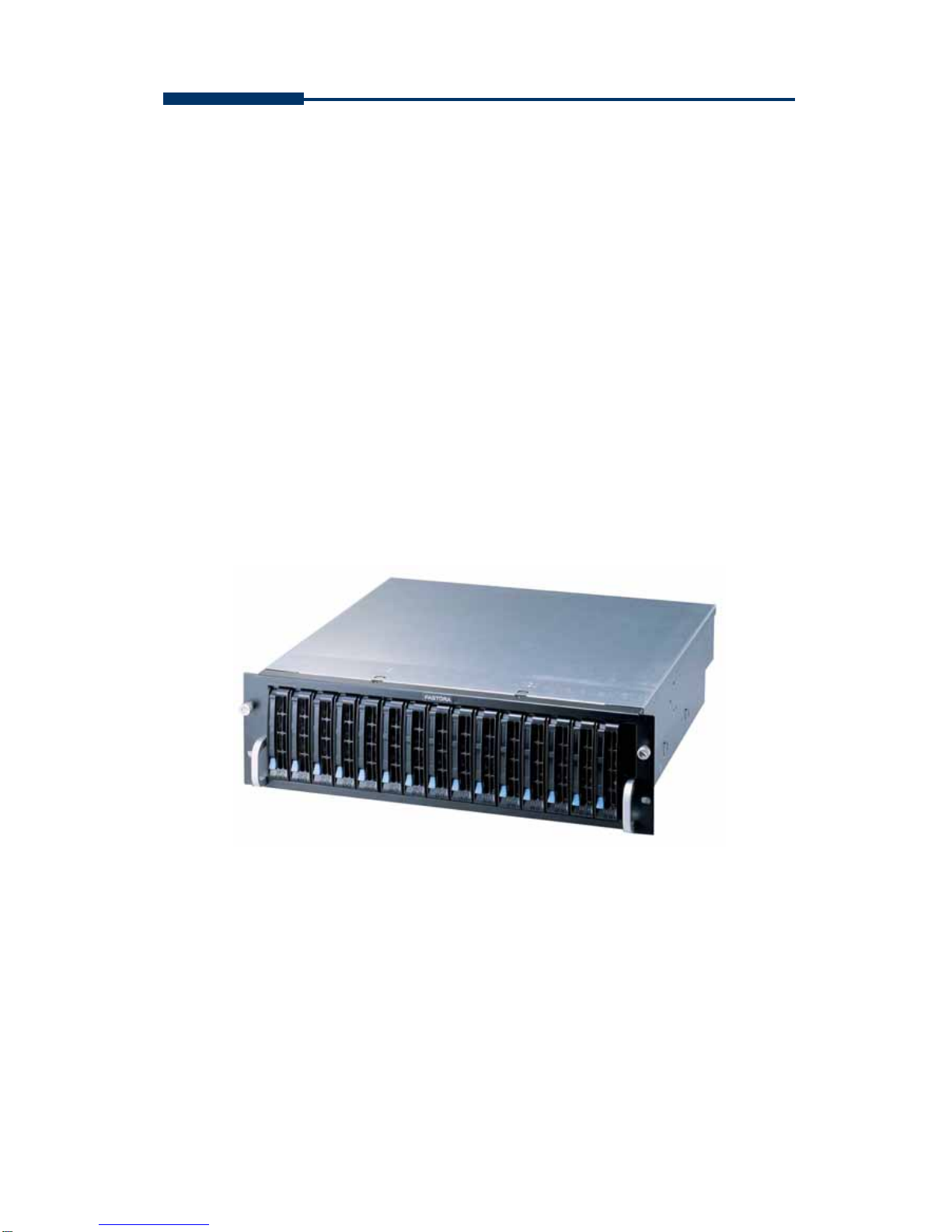
FASTORA DAS-315SA Disk Array
2
The information in this guide may be changed without notice. We assume no
responsibility for any errors which may appear in this guide. The FASTORA
DAS-315SA is a trademark of FASTORA. Microsoft, Windows and Windows
logo are trademarks of Microsoft Corporation.
Copyright 2004. All rights reserved. No Part of the contents in this guide may
be transmitted or reproduced in any form or by any means without the written
permission of the manufacturer. Printed in Taiwan.
The revision date for this guide is May 26, 2004
Version 1.02
FCC Statement
This equipment has been tested and found to comply with the limits for a Class
A digital device, pursuant to Part 15 of the FCC Rules. These limits are
designed to provide reasonable protection against harmful interference in a
residential installation.
This equipment generates and can radiate radio frequency energy and, if not
installed and used according to the instructions, may cause harmful
interference to radio communications. However, there is no guarantee that
interference will not occur in a particular installation. If this equipment does
cause harmful interference to radio or television reception, which is found by
turning the equipment off and on, the user is encouraged to try to correct the
interference by one or more of the following measures:
--Reorient or relocate the receiving antenna
--Increase the separation between the equipment and device
--Connect the equipment to an outlet other than the receiver
--Consult a dealer or an experienced radio/TV technician for assistance
CE Mark Warning
This is a Class A product. In a domestic environment, this product may cause
radio interference in which case the user may be required to take adequate
measures.