Extron electronics M Series Manuel utilisateur

Manual M-series
MA1479-1.doc
Monitoring M-series
Manual
19” and Wall
English
Manual for M-series monitoring unit
with firmware ver. 102 and later.
For support and information:
Extron AS
Tel: (+47) 63 83 33 90
Mobile: (+47) 90 03 23 94
www.extron.no
Nedre Rælingsvei 261
N-2008 FJERDINGBY

Manual M-series
MA1479-1.doc
2/15
Foreword
M-series are monitoring units for DC-systems with voltage range 9 – 300 VDC.
For monitoring of DC-voltage, DC-current, earth fault and AC-voltage and also triggering of
battery test. Settings are easily made with buttons on the front panel and momentary
value/setting is shown in the display. For advanced settings there is a service menu.
M-series is available both as 19” and wall-mount.
Difference between the M-series models
M100
M200
M300
Display of DC-voltage ● ● ●
Display of current
●
Display of AC-voltage
●
Display of earth fault value ● ● ●
High DC voltage alarm
●
●
●
Low DC voltage alarm 1 ● ● ●
Low DC voltage alarm 2
●
●
●
Earth fault
●
●
●
Battery test (circuit/capacity) ●
Mains fault
●
Powered by DC ● ● ●
Separate relays for every alarm
●
●
Sum alarm relay
●
●
●
The front panels are different according to illustration below. M300 has all that M100/M200
offers and also display of current, mains voltage and buttons for battery test (start/stop,
interval, length) and mains fault delay. Levels for battery test and mains fault are adjusted in
the service menu (see other chapter).
M300 M200
M200
M300

Manual M-series
MA1479-1.doc
3/15
Installation 19”
Unpack
Open box and find follow parts:
1 pcs. monitoring unit M-series
1 pcs. manual
1 pcs. set of male connectors for connection on backside
1 pcs. connected cable for earth fault sensing
1 pcs. set of attached nuts and washers on earth bolt
Install the unit in the 19” rack and connect safety earth cable, DC-power and signaling
cables.
Never do a high-pot test without disconnecting the earth fault sensor cable.
Disconnect this cable before doing the test.
The unit starts automatically when DC-power is connected.
Installation Wall
Unpack
Open box and find follow parts:
1 pcs. monitoring unit M-series
1 pcs. manual
1 pcs. set of male connectors for connection inside
1 pcs. connected cable for earth fault sensing
Option: 2 pcs. of brackets for door-mounting incl. screws and washers
Wall-mounting
Unscrew the screws on the four sides and remove the front panel. Fasten the back side
against the wall by using the four holes at each corner inside. Connect the cables for safety
earth (preferably the same screw as for earth sensor), DC-power and signaling. Use the wire
pull protections. Finally fasten the front panel again with the four screws.
Door mounting
Unscrew the screws on the four sides and remove the front panel. Fasten the mounting
brackets (option) with the screws. Fasten the front panel against the door. Connect the
cables for safety earth (preferably the same screw as for earth sensor), DC-power and
signaling. Use the wire pull protections. Fasten the back side using the screws.
Never do a high-pot test without disconnecting the earth fault sensor cable.
Disconnect this cable before doing the test.
The unit starts automatically when DC-power is connected.

Manual M-series
MA1479-1.doc
4/15
Connections left
Illustration for M300 19”. M100/200 has fewer connections which is shown by the label on
the unit. The wall model has the corresponding connectors internally as the 19”. For
connection of the safety earth on Wall model use the same screw as for earth fault sensing.
Mains alarm relay in/out (only M300), Used with
external main fault relay. UT gives 5V which are
connected to the relay and returned to IN. The input
can be inverted with a setting in the service menu. Do
not use at the same time as AC-input (see below.
Shunt +/- (only M300), for connection of current
shunt. The shunt must be connected to minus side.
Different values for shunts can be used. Max 60mV.
The unit is precalibrated for 100A/60mV. Calibration
for other shunts are made in the service menu.
Earth fault sensing, connects to the safety earth bolt.
Disconnect when doing hi-pot test.
DC, for powering the unit and for measuring of DC-
voltage. Depending on model: 9-36VDC, 30-75VDC or
70-300VDC.
AC N and L (only M300), for connecting of mains
voltage to measure voltage level and mains fault. Not
used for powering the unit. Do not use at the same
time as external main fault relay (see above).
Earth stud, connection of safety earth and earth fault
sensor.

Manual M-series
MA1479-1.doc
5/15
Connections left
Illustration for M300 19”. M100/200 has fewer connections which is shown by the label on
the unit. The wall model has the corresponding connectors internally as the 19”.
Relay outputs
B open when alarm
S closed when alarm
G common
Mains fault (only M300)
Low DC voltage 2 (only M200/300)
Battery test, for triggering a rectifier (only M300)
Battery test, for faulty battery test (only M300)
High DC voltage (only M200/300)
Low DC voltage 1 (only M200/300)
Earth fault (only M200/300)
Sum alarm (all models)

Manual M-series
MA1479-1.doc
6/15
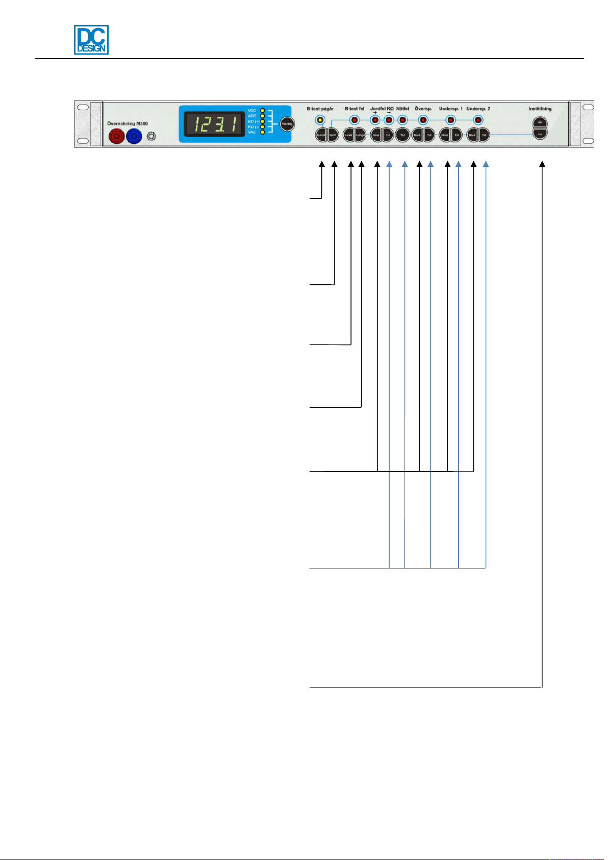
Front panel
Below is explanation of front panel. The different models in the M-series are different in form
and function and all features may not be present on delivered unit.
Measurement connectors, display, display indicators and display button
Alarm indicators and the battery test indicator
Buttons for choosing what to display
Indicators for what is displayed
The display shows momentary values or adjustment
value (by pressing adjustment button. VDC: 0-
300VDC. ADC: depends on shunt. KΩ(+)KΩ(-): 0-
1000KΩ, above 1000KΩ display shows ”----”. VAC:
0-250VAC, above 250 VAC display shows ”----”.
Earth connector (not for safety earth)
Measurement connector for V-meter. Short circuit
protected.
Red alarm indicators. Flashes when each alarm
has been triggered. If set delay is reached the
indicator goes into latched state (and the relay is
closed) and does not stop flashing until the alarm
is gone and the reset-button is pressed. Note:
battery fault goes into latched state instantly
without delay. Automatic resetting (no latching)
can be enabled in the service menu.
Yellow battery test indicator. Flashing when
battery test is in progress. Manually started or
auto.
Manual M-series
MA1479-1.doc
7/15
Buttons
B-test: Start/stop battery test. If no battery
test is in progress the battery test is started
with the length that is set by using the
”length-button”. If pressed while battery test
is in progress the battery test is stopped.
Both manual and automatically started tests
can be stopped.
Reset: Alarm reset. Flashing alarm
indicators with no alarms active stops
flashing.
I-val: Battery test interval. For setting of
time between start of battery tests.
Possible: Off, 1 day, 30 days, 90 days and
180 days.
Length: Battery test length. Possible: 5 sec
(circuit test), 15 min, 30 min, 1 hour, 2
hours, 4 hours.
Level buttons for earth fault, high DC
voltage, low DC voltage 1 and low DC
voltage 2.
Earth fault: 50-1000Kohm.
High DC voltage, low DC voltage and low
DC voltage 2: 1-300VDC
Delay buttons. Delay of earth fault, mains
fault, high DC voltage, low DC voltage 1
and low DC voltage 2. Possible: 1-1800
sek. Above 1800 sec blocks the alarm and
is indicated with ”bloc” in the display.
Blocking blocks both alarm indicators and
relay.
Button (+) and button (-), press each
adjustment button to the left and press
these buttons to increase (+) and decrease

Manual M-series
MA1479-1.doc
8/15
Service menu
The service menu is used for calibration and other settings. It is used when testing the unit
before leaving the factory and can be used when the installer wants to adapt the units in a
more advanced way than is being offered by only using the normal settings. Use the service
menu with care.
Enter/exit the service menu and navigation
Enter the service menu by holding in the level
buttons for high DC voltage and for low DC voltage
2. The display shows an animation. Keep holding
the buttons until ”On” is displayed. Release the
buttons. The number ”0” is shown which is the
service menu.
Navigate to the menus with +/-. Then push the
button “Display” and use +/- to change the setting.
Available menus are listed on next page.
The service menu is exit the same way as it is
entered. By holding in the level buttons for high DC
voltage and for low DC voltage 2. The display
shows an animation. Keep holding the buttons until
”Off” is displayed. Release the buttons.
The service menu is automatically shut off after 5
minutes of no button presses.

Manual M-series
MA1479-1.doc
9/15
List of service menu settings
Choose the menu by pressing +/-. Start adjusting the setting by pressing Display button and
+/-.
0
LED/indicator test.
All indicators on the front panel and all segments in the 4-digit display is lit.
1
Relay-test.
Press the Display button and push +/- to test each relay. Which relay that is tested is
indicated on the indicators for each alarm and also with words in the 4-digit display.
2
Set all levels to factory default.
Recalls the factory defaults for high DC voltage, low DC voltage 1, low DC voltage 2 and
battery test depending on selected nominal voltage. Press display button and use +/-.
Voltage
High DC voltage
Low DC voltage 1
Low DC voltage 2
Battery test
12 V
14.0 V
11.4 V
10.2 V
11.8 V
24 V
28.0 V
22.8 V
20.4 V
23.5 V
36 V
41.9 V
34.2 V
30.6 V
35.3 V
48 V
55.9 V
45.6 V
40.8 V
47.0 V
60 V
69.9 V
57.0 V
51.0 V
58.8 V
108 V
125.8 V
102.6 V
91.8 V
105.8 V
120 V
139.8 V
114.0 V
102.0 V
117.6 V
216 V
251.6 V
205.2 V
183.6 V
211.7 V
The nominal voltage is set from factory if specified by order specifications. If no order
specification is told then the voltages are: 12-24: 24V, 36-60V: 48V, 110-220V: 108V.
3
M-series model.
M100, M200 or M300. Governs the different choices possible for display values and which
alarm can be used. Press Display button and use +/-. The correct model is set from the
factory.

Manual M-series
MA1479-1.doc
10/15
4
Calibration of DC-voltage.
Connect calibrated V-meter in the V-meter output. Press Display button and use +/- to set
the same value in display as the V-meter is showing. Release Display button. Calibration is
finished. Calibration of earth fault display is recommended after calibration of voltage. The
unit is calibrated before delivery from factory.
5
Calibration of earth fault.
Check that no earth fault is present or disconnect the earth fault sensing cable. Press
Display button (without holding) to start the calibration. The display shows an animation and
the calibration is done automatically. The calibration is done when “done” is shown in the
display. Make sure the calibration if DC-voltage is done before calibration of earth fault. The
unit is calibrated before delivery from factory.
6
Calibration of current display zero-value (only M300).
This menu is not active in units with firmware ver. 102 and later. The Display button can be
pressed and Done will be shown in order to replicate earlier versions but it doesn’t do
anything.
7
Calibration of current display (only M300).
Use calibrated A-meter as reference. Increase the current over the shunt to max. Press
Display button and use +/- to set the same value in the display as the A-meter is showing.
Release Display button. The calibration is now finished. If the display current value is still not
correct try calibrating the zero-value first and retry calibrating the current display. The unit is
calibrated for a 100A/60mV shunt from factory.
8
Calibration of mains voltage display (only M300).
Connect external V-meter to the main voltage. Press Display button and use +/- to set the
same value as the V-meter is showing. Release Display button. The calibration is now
finished.
The unit is calibrated before delivery from factory.
Ce manuel convient aux modèles suivants
3
Table des matières
Manuels Instrument de mesure populaires d'autres marques


Endress+Hauser
Endress+Hauser Proline Promag 50 Caractéristiques techniques

Siemens
Siemens SITRANS F Coriolis FCT030 Manuel de la liste des pièces

KLINGER
KLINGER CMF V Series Manuel utilisateur

EXFO
EXFO FTB-2 Manuel d'exploitation et d'entretien

Keysight
Keysight M8290A Manuel utilisateur

ADTEK
ADTEK MW-5 Manuel utilisateur