ETAS ES1337.2 Manuel utilisateur

ES1337.2 Wheel Speed Sensor Simulation Board
User’s Guide

2
Copyright
The data in this document may not be altered or amended without special
notification from ETAS GmbH. ETAS GmbH undertakes no further obligation
in relation to this document. The software described in it can only be used if
the customer is in possession of a general license agreement or single license.
Using and copying is only allowed in concurrence with the specifications
stipulated in the contract.
Under no circumstances may any part of this document be copied, repro-
duced, transmitted, stored in a retrieval system or translated into another
language without the express written permission of ETAS GmbH.
© Copyright 2018 ETAS GmbH, Stuttgart
The names and designations used in this document are trademarks or brands
belonging to the respective owners.
V1.0.0 R03 EN - 07.2018

Contents 3
Contents
1Introduction . . . . . . . . . . . . . . . . . . . . . . . . . . . . . . . . . . . . . . . . . . . . . . . . . . . . . 5
1.1 Areas of Use and Features . . . . . . . . . . . . . . . . . . . . . . . . . . . . . . . . . . . . . 5
1.2 Block Diagram . . . . . . . . . . . . . . . . . . . . . . . . . . . . . . . . . . . . . . . . . . . . . 8
1.3 Taking the Product Back and Recycling . . . . . . . . . . . . . . . . . . . . . . . . . . . 9
2Hardware Features . . . . . . . . . . . . . . . . . . . . . . . . . . . . . . . . . . . . . . . . . . . . . . . 11
2.1 Wheel Speed Sensors . . . . . . . . . . . . . . . . . . . . . . . . . . . . . . . . . . . . . . . 11
2.1.1 Type “DF6” . . . . . . . . . . . . . . . . . . . . . . . . . . . . . . . . . . . . . . . 12
2.1.2 Type “DF10” . . . . . . . . . . . . . . . . . . . . . . . . . . . . . . . . . . . . . . 13
2.1.3 Type “DF10-RotDir” . . . . . . . . . . . . . . . . . . . . . . . . . . . . . . . . . 14
2.1.4 Type “DF11i” . . . . . . . . . . . . . . . . . . . . . . . . . . . . . . . . . . . . . . 15
2.1.5 Type “VDA”. . . . . . . . . . . . . . . . . . . . . . . . . . . . . . . . . . . . . . . 17
2.2 Analog Outputs . . . . . . . . . . . . . . . . . . . . . . . . . . . . . . . . . . . . . . . . . . . . 19
2.2.1 Reference Voltages. . . . . . . . . . . . . . . . . . . . . . . . . . . . . . . . . . 19
2.2.2 Type of Output Signal. . . . . . . . . . . . . . . . . . . . . . . . . . . . . . . . 19
2.2.3 Disabling the Output . . . . . . . . . . . . . . . . . . . . . . . . . . . . . . . . 19
2.3 Synchronization Signal . . . . . . . . . . . . . . . . . . . . . . . . . . . . . . . . . . . . . . 19
3Pin Assignment and Display Elements . . . . . . . . . . . . . . . . . . . . . . . . . . . . . . . . . 21
3.1 Pin Assignment . . . . . . . . . . . . . . . . . . . . . . . . . . . . . . . . . . . . . . . . . . . . 21
3.1.1 “OUTPUT 0-5” Signal Outputs . . . . . . . . . . . . . . . . . . . . . . . . . 21

Contents4
3.1.2 “SYNC” Port . . . . . . . . . . . . . . . . . . . . . . . . . . . . . . . . . . . . . . 22
3.2 LEDs . . . . . . . . . . . . . . . . . . . . . . . . . . . . . . . . . . . . . . . . . . . . . . . . . . . . 23
4Technical Data . . . . . . . . . . . . . . . . . . . . . . . . . . . . . . . . . . . . . . . . . . . . . . . . . . 25
5ETAS Contact Addresses. . . . . . . . . . . . . . . . . . . . . . . . . . . . . . . . . . . . . . . . . . . 27
Index . . . . . . . . . . . . . . . . . . . . . . . . . . . . . . . . . . . . . . . . . . . . . . . . . . . . . . . . . 29

Introduction 5
1 Introduction
This User’s Guide describes the ES1337.2 Signal Generator Board.
This section contains information on the basic functions and the area of use of
the ES1337.2 Signal Generator Board.
1.1 Areas of Use and Features
The correct determination of the wheel speed by wheel speed sensors is an
important prerequisite for the functioning of lots of ECUs for controlling the
braking force on each individual wheel (ABS, TCS and ESP). The control pre-
vents either the wheels blocking or the wheels spinning in an uncontrolled
manner. Navigation systems also access vehicle speed when the GPS signal is
weak or non-existent.
Wheel speed sensors are available in two basic designs:
• a passive design, in which the sensor element does not require an
external power supply
• an active design with an external power supply of the sensor element
The designs also differ in terms of the physical effect, on which the acquisition
of the wheel speeds is based, and the scope and content of the information
provided by the sensor.
CAUTION!
Some components of the ES1337.2 Signal Generator Board may
be damaged or even destroyed by static discharge. Leave the
board in its transport package until you want to install it.
The ES1337.2 Signal Generator Board should only be taken from
its package, configured and installed at a working place that is
protected against static discharge.
WARNING!
The components, connectors and conductors of the ES1337.2
Signal Generator Board may carry dangerous voltages. These volt-
ages may even exist if the ES1337.2 is not installed in the ES4100
or the ES4105 and the ES4100 or the ES4105 is powered off.
Make sure the ES1337.2 is protected against contact during oper-
ation. Disconnect all connectors to the ES1337.2 before removing
the board.

Introduction6
Features
The ES1337.2 Signal Generator Board has four independent signal generators
for generating various sensor signals. The following types of sensor can be
simulated:
• Passive analog sensors with a sinusoidal output signal (type “DF6”)
• Active digital sensors with a current interface with two current levels
(type “DF10”)
• Active digital sensors with a current interface with three current levels
and forwards/backwards coding (type “DF10-RotDir”)
• Active digital sensors with a current interface with two current levels
and additional information (type “DF11i”)
• Active digital sensors with a current interface with three current levels
and additional information (type “VDA”)
In addition, there are two other galvanically isolated analog voltage outputs.
The ES1337.2 Signal Generator Board has the following features:
• Four identical, galvanically isolated signal generators for generating
speed signals
• Outputs: ±10 V and 0...40 mA with 10-bit resolution
• Two identical, galvanically isolated analog outputs:
– ±10 V with 10-bit resolution
– Configurable reference voltages (internal/external)
• Every channel is protected against overvoltages to ±60 V
• All outputs with a cut-off relay
• Stand still detection (DF11i, VDA) is supported
• Mixed sensor configurations possible
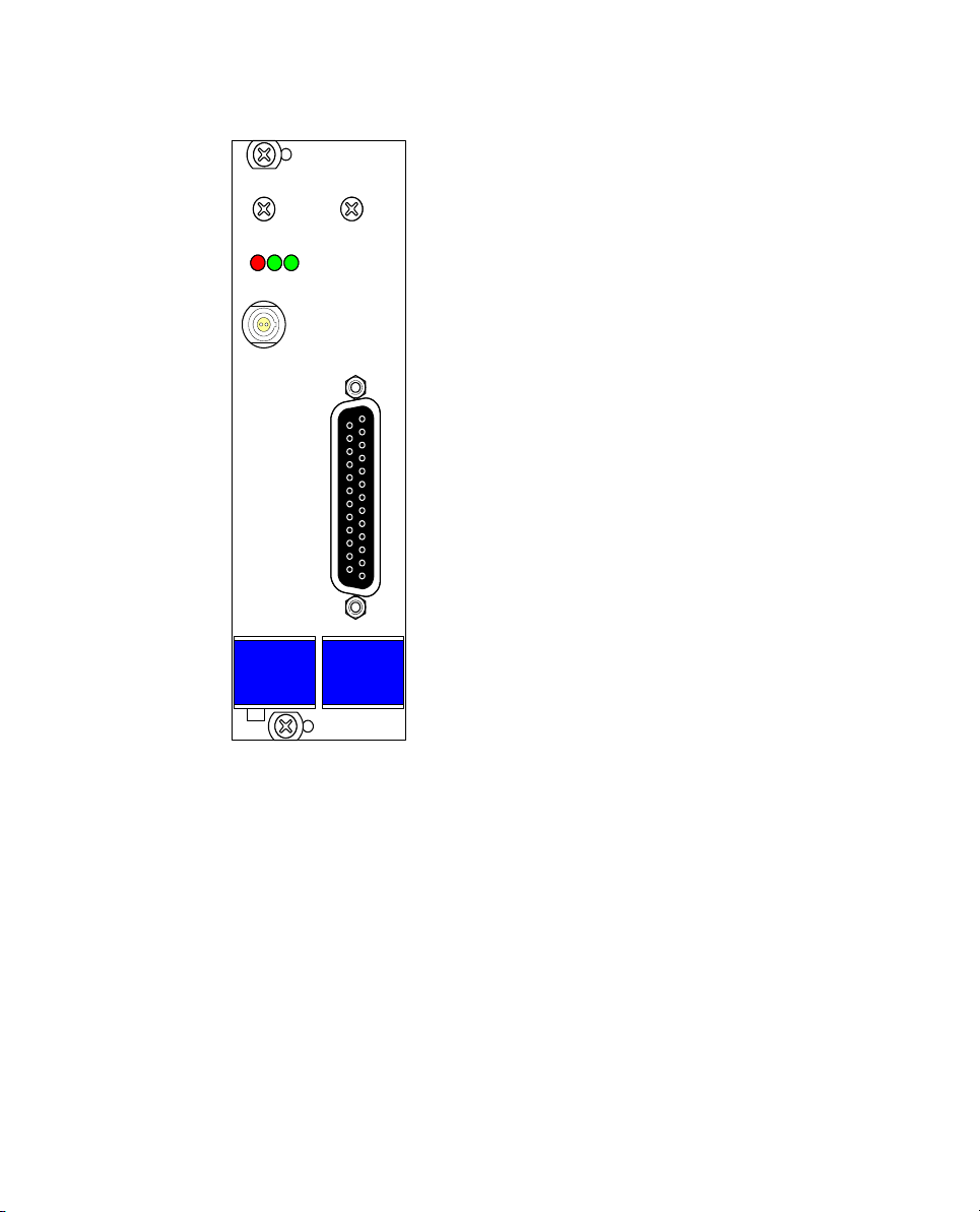
The following figure shows the front panel of the ES1337.2 Signal Generator
Board with
• the LEDs (see "LEDs" on page 23)
• the port for the signal outputs, signal grounds and external reference
voltages (see "“OUTPUT 0-5” Signal Outputs" on page 21).
• the “SYNC” port (see "“SYNC” Port" on page 22) for outputting a
synchronization signal (“tooth 0”), for example to an oscilloscope.

Introduction 7
Fig. 1-1 Front View of the ES1337.2 Signal Generator Board
ES1337.1
ETAS
L0ER L1
SYNC
OUTPUT 0-5

Introduction8
1.2 Block Diagram
Fig. 1-2 shows a block diagram with all important function units of the
ES1337.2 Signal Generator Board.
Fig. 1-2 Block Diagram of the ES1337.2 Signal Generator Board
FPGA Controller
Output 0-5
VMEbus Interface
Output Multiplexer
Analog Outputs Wheel Speed Signal
Generator 0...3
Rotational Speed
Generator
Control Register
SYNC
Output 0...3
Output
Protection
Current
Interface
Output 4...5
Output
Protection

Introduction 9
1.3 Taking the Product Back and Recycling
The European Union has passed a directive called Waste Electrical and Elec-
tronic Equipment, or WEEE for short, to ensure that systems are setup
throughout the EU for the collection, treating and recycling of electronic
waste.
This ensures that the devices are recycled in a resource-saving way represent-
ing no danger to health or the environment.
Fig. 1-3 WEEE Symbol
The WEEE symbol on the product or its packaging shows that the product
must not be disposed of as residual garbage.
The user is obliged to collect the old devices separately and return them to the
WEEE take-back system for recycling.
The WEEE directive concerns all ETAS devices but not external cables or batter-
ies.
For more information on the ETAS GmbH Recycling Program, contact the ETAS
sales and service locations (see "ETAS Contact Addresses" on page 27).

Introduction10
Table des matières
Manuels Matériel réseau populaires d'autres marques

Matrix Switch Corporation
Matrix Switch Corporation MSC-HD161DEL Manuel utilisateur

B&B Electronics
B&B Electronics ZXT9-IO-222R2 Manuel utilisateur

Yudor
Yudor YDS-16 Manuel utilisateur

D-Link
D-Link ShareCenter DNS-320L Manuel utilisateur

Samsung
Samsung ES1642dc Instructions d'utilisation

Honeywell Home
Honeywell Home LTEM-PV Instructions de montage


