ERA KP700 Manuel utilisateur

Wireless Keypad
KP700

CONTENTS
1. INTRODUCTION
Introduction
Package Contents
Features
2. BEFORE USE
Power On
Connecting
Installation
3. SETTINGS
Enter setup state
Exit Delay
SOS key
Keyboard Tone
RFID reader setting
Direct disarm by RFID tag
Change user code
Change admin code
Reset
4. USAGE
Arm
Disarm
Stay mode
Emergency Call
Mute Mode
5. NOTICES
& MAINTENANCE
Usage notices
Maintenance
6. FAQ
7. INSTRUCTIONS OF
WIRED CABLES
INTERFACE
8. SPECIFICATIONS
1
1
2
3
4,5
5
6
6,7
7
8
8,9
9,10
10,11
11
11
12
12,13
13
14
14
15
15
16
17
17

1.INTRODUCTION
Thank you for purchasing this wireless keypad.
This can be installed inside or outside the home and allows the user to arm,
disarm alarm after inputting passcode.
This keypad can also connect to an automatic door lock.
KIT CONTENTS
Keypad x 1
AAA 1.5V battery x 3
Screws x 4
Manual x 1
Wired cable x1
Note: RFID tags (125KHz) can be purchased separately. Max. 50 pieces are supported.
RFID Tag
1
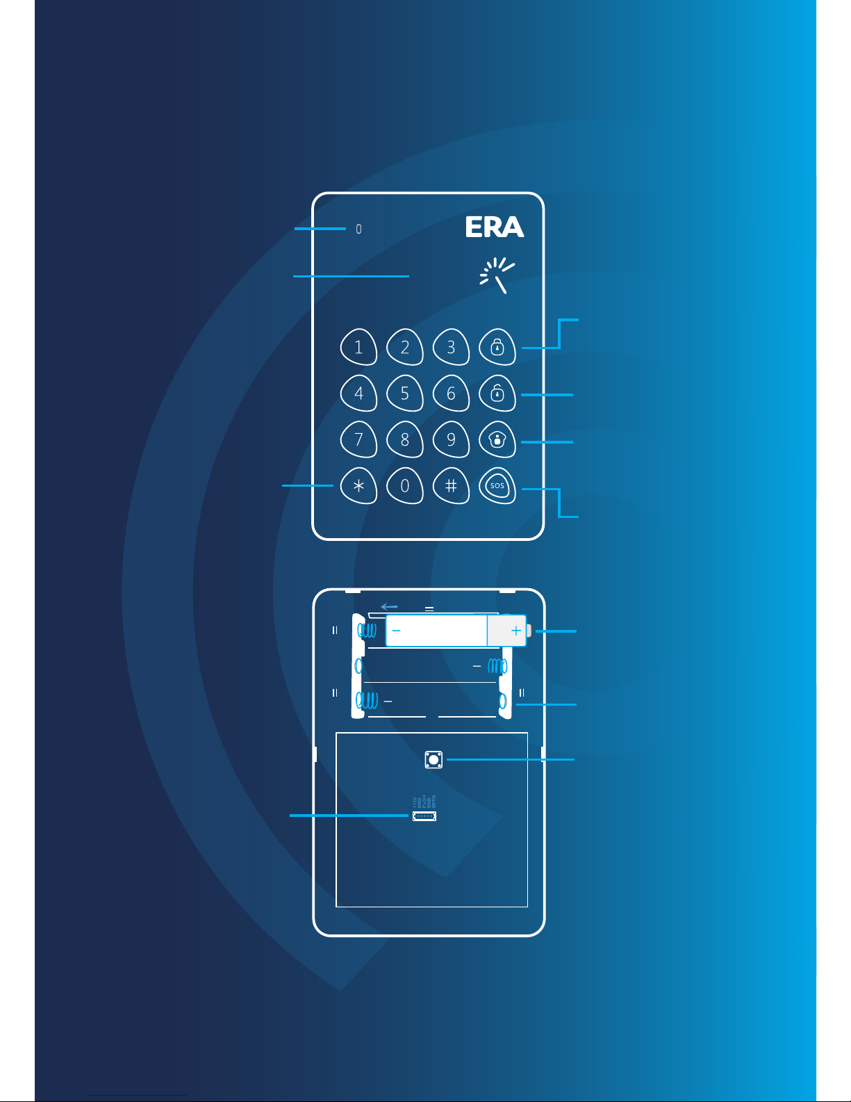
LED indicator
Arm
Disarm
Stay mode
SOS key
RFID wake-up key
RFID reader
FEATURES
Positive & negative
terminals for battery
Battery compartment
Tamper switch
Wired cable
interface
+
+
AAA
Note: The keypad beeps twice every two seconds & LED indicator flashes once in case of
low battery.
2

2.BEFORE USE
POWER ON
Remove the insulating strip for the first time.
Keypad uses 3x AAA batteries.
Loose the screw, open the case
Put batteries in according to the positive and negative signs.
Close the rear cover and screw on.
+
+
AAA
123
1
3
2
Note: Opening the rear cover of keypad will trigger the tamper switch, please dismiss the
alarm by following the disarm instruction (page 12)
When connected with electronic door lock as an access control, keypad is
suggested to use the specific power supply for access control.
To know connection steps, please refer to the instruction manual of electronic
door lock. The electronic door lock and specific power supply for access control
should be purchased respectively.
3

CONNECTING
CONNECTING KEYPAD TO CONTROL PANEL
Make sure the control panel is in connecting state, input user code or admin
code on keypad, and then press any key of [Arm] [Disarm] [Stay Mode]. The
connection succeeds after one beep.
1
2
1
2
Default User Code: 1234
Default Admin Code: 123456
User can remotely control the panel via the keypad after connection; for detailed
connection steps, please refer to the user manuals of panels.
Note: If the control panel beeps twice when connecting, it means the keypad has already
connected with the panel.
CONNECTING KEYPAD TO PERSONALISED TAG (RFID)
Press [9], one beep is heard and the LED indicator is on. Keypad enters
learning state.
Input [admin code + #] to wake up keypad.
Three beeps mean wrong input.
1
1
2
2
4

Note: Wrong input for 6 times continuously, the keypad will be locked for 20 seconds.
3
Put RFID tag close to the RFID reader, the connection succeeds after
one beep and the LED indicator goes out.
3
CONNECTING ELECTRONIC DOOR LOCK
Please refer to the instruction manual of electronic door lock.
INSTALLATION
If two beeps are heard, it indicates the RFID tag has been connected before.
To clear the connection of RFID tags, input [admin code + #] to wake up the
keypad and then press down [9] for six seconds. RFID tags are all cleared after
one beep.
Fix the keypad on the door frame or the wall before use.
1 2 3
Loose the screw, open the case
Fix the rear cover on the door frame or the wall by screws
Fasten the front cover of keypad on the rear cover. Secure two covers into place
and then screw on
1
3
2
Note: Opening the rear cover of keypad will trigger tamper switch, please dismiss the alarm
by following the disarm instruction (page 12)
5

3.SETTINGS
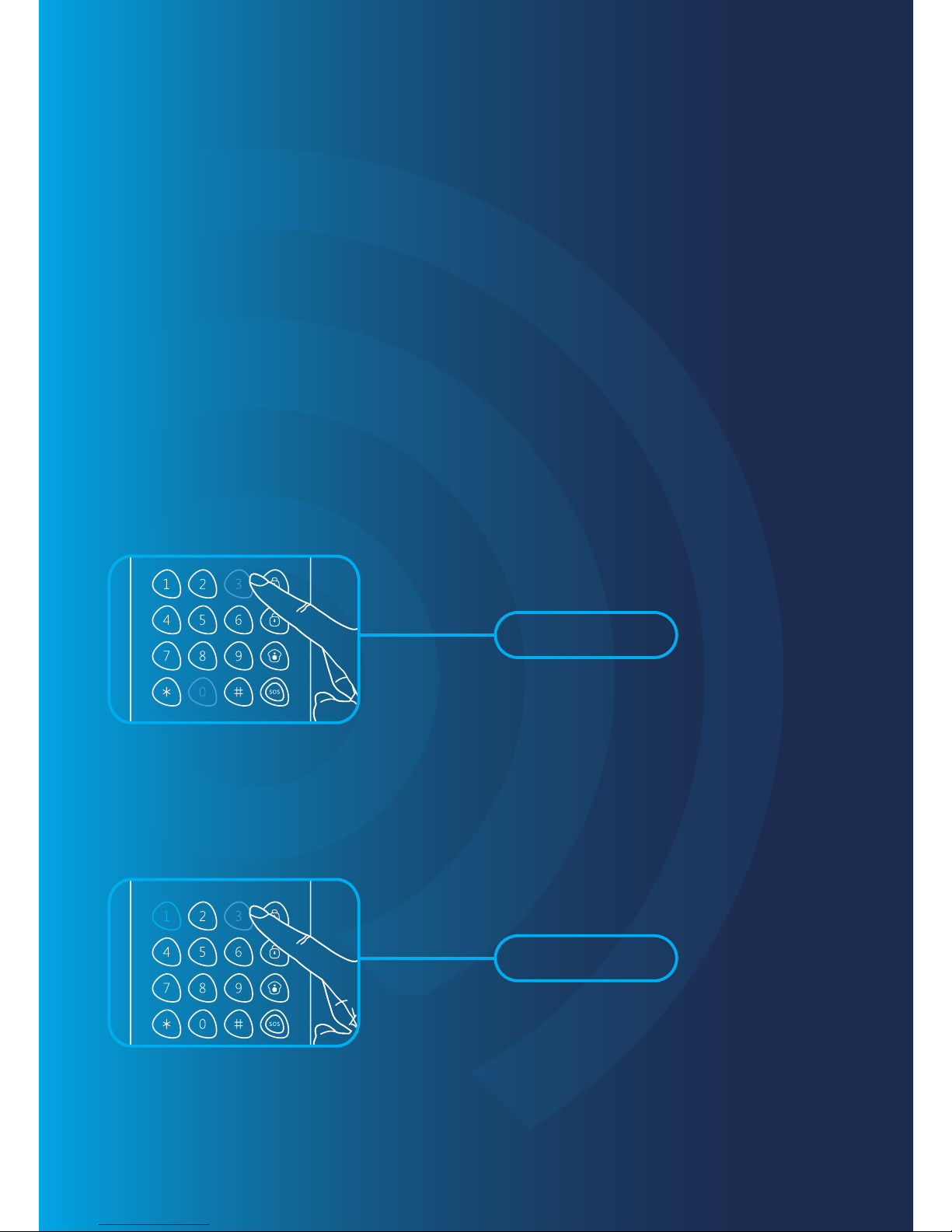
ENTER SETUP STATE
The keypad should enter setup state before all settings.
Input [admin code + #] to wake up keypad.
Press [3] to enter setup state, the LED indicator is on.
1
1
2
Under setup state, if there is no operation within 10 seconds, the keypad will exit
setup state automatically. You can also press [#] to exit.
2
EXIT DELAY
The exit delay allows time to leave after arming the system. After the delay time, if
you are sill at home, you may trigger an alarm.
This setting does not apply to Stay Mode.
If the delay time of both control panel and keypad are set delay time respectively,
the actual delay time is the total of both times.
Enter setup state, input:
*2*delay time*
6
When one beep is heard and the LED indicator keeps on for 10 seconds, the
setup is successful.
Once the delay time is set, when you arm the keypad, it will beep once every
two seconds to remind you to leave. The reminding rhythm will speed up in
the last 15 seconds. After the delay time, the control panel enters arm state.
Note: User can input digital 0-250 which refers to 0-250 seconds.
Default setting: 0, no delay.
SOS KEY
You can choose to input code before pressing [SOS] key or not. This function
is to prevent false operation or trick.
Enter setup state, input:
*3*0*
When one beep is heard and the LED indicator keeps on for 10 seconds, the
setup is successful.
NOT INPUT CODE FOR SOS
Enter setup state, input:
*3*1*
When one beep is heard and the LED indicator keeps on for 10 seconds, the
setup is successful.
ENABLE CODE SOS
Note: Default setting: 0, Code SOS is disabled.
7

KEYBOARD TONE
Keyboard tone can be turned on or off.
If it is off, the successful setup tone will be closed too.
Enter setup state, input:
*4*0*
When one beep is heard and the LED indicator keeps on for 10 seconds, the
setup is successful.
TURN OFF KEYBOARD TONE
Enter setup state, input:
*4*1*
When one beep is heard and the LED indicator keeps on for 10 seconds, the
setup is successful.
TURN ON KEYBOARD TONE
Note: Default setting: 1, turn on the keyboard tone.
RFID READER
DISABLE RFID READER
Enter setup state, input:
*5*0*
8
Table des matières


