ELECTRIC HEATERS • O. & M.
8©March, 2007 Environmental Technologies
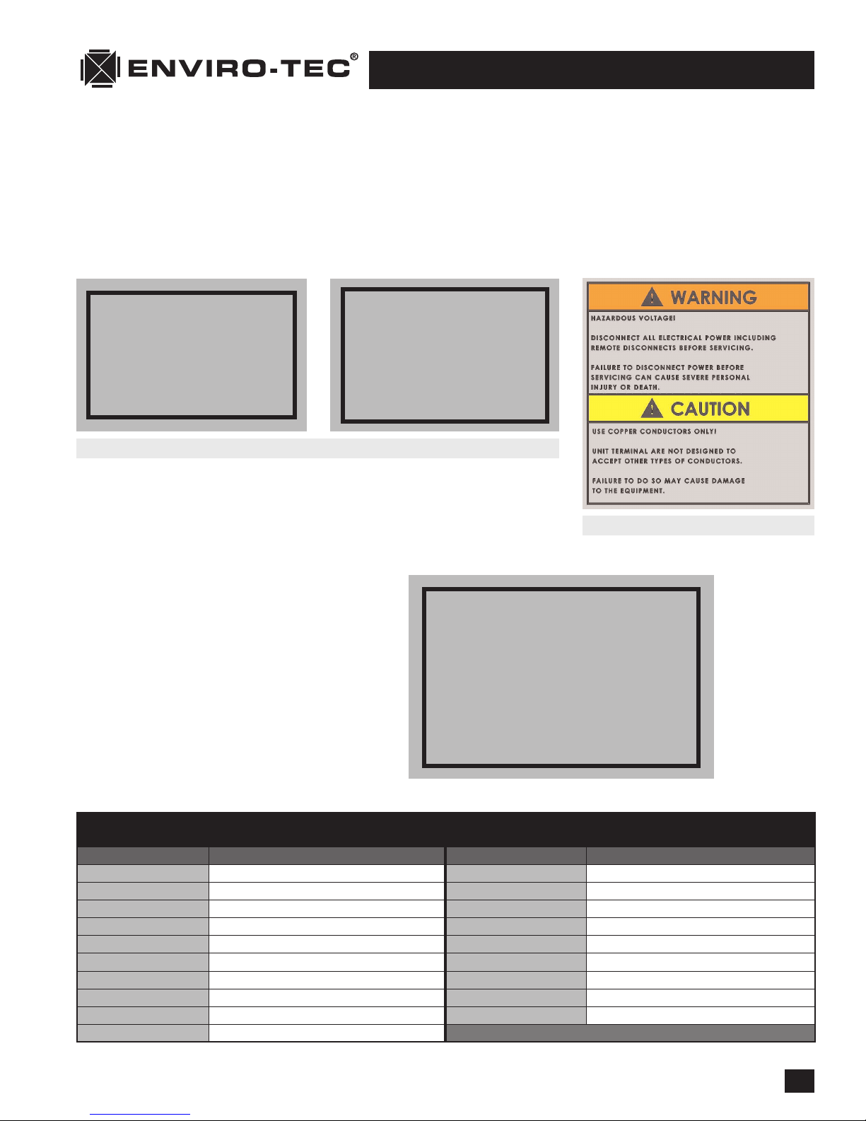
CAUTION: Lethal voltages are present in the heater control enclosure. Use extreme caution
when taking measurements in these units. Always disconnect power before
removing or re-applying any connections.
1. Before applying power, verify wiring matches diagram in cover of heater control enclosure, and that cor-
rect line voltage has been wired to heater line block.
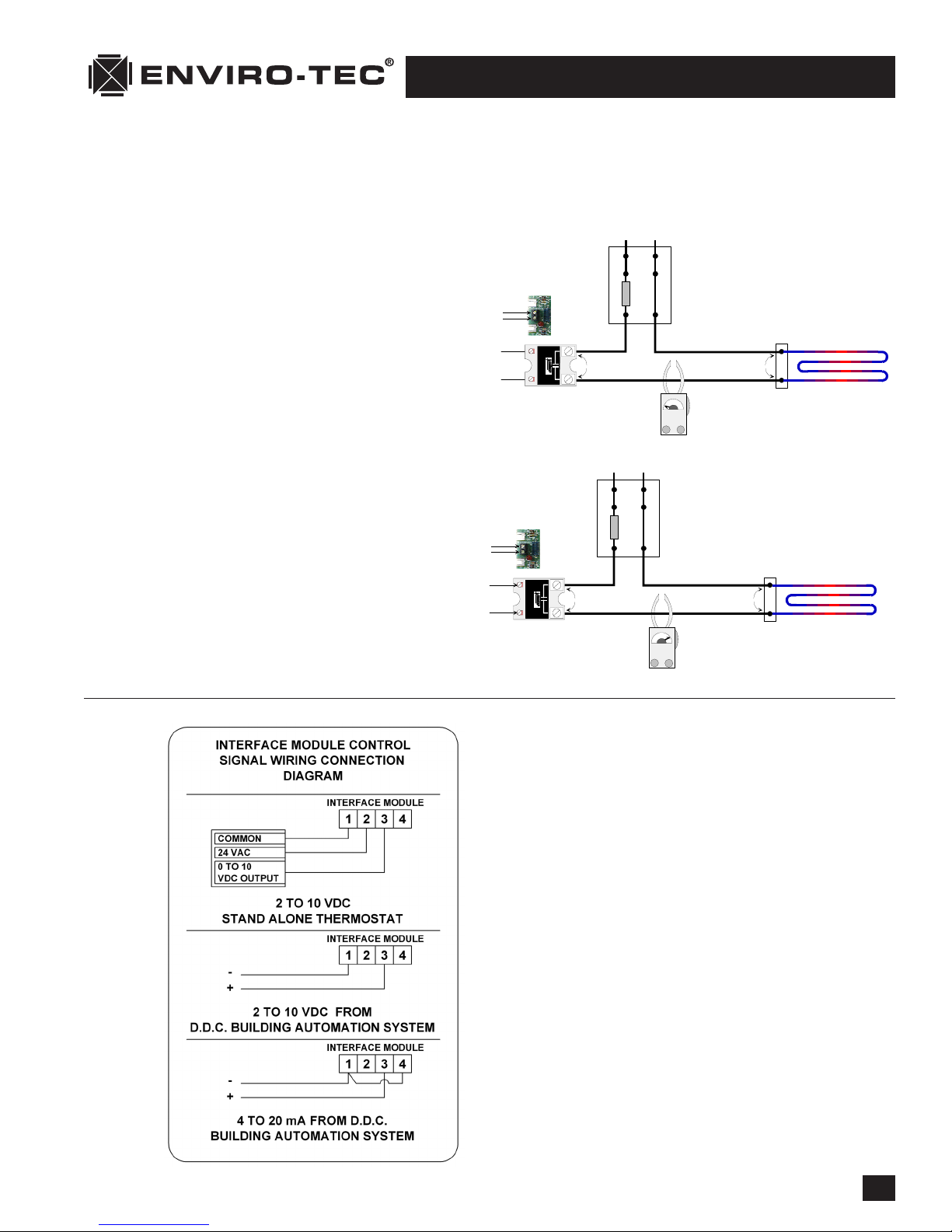
2. Verify 24 VAC +15% or -10% between P1 and P2 of interface circuit board (ETPHCI, ETPHCV2, etc., depend-
ing on input).
3. The table below lists responses to input signal by interface model as explained in step 4. If any of these
inputs cannot be obtained, refer to the literature on the device that is supposed to provide the input.
Otherwise, proceed to step 4.
INTERFACE “PULSE” FULL OFF FULL ON INPUTS
MODEL INPUT INPUT INPUT
ETPHCI 12.0 mA 4.0 mA 20.0 mA Sig, Com
ETPHCV2 6.0 VDC 2.0 VDC 10.0 VDC Sig, Com
ETPHCC 50% 0 VAC 24 VAC Sig, Com
ETPHCC1 50% 0 VAC 24 VAC +18, Com
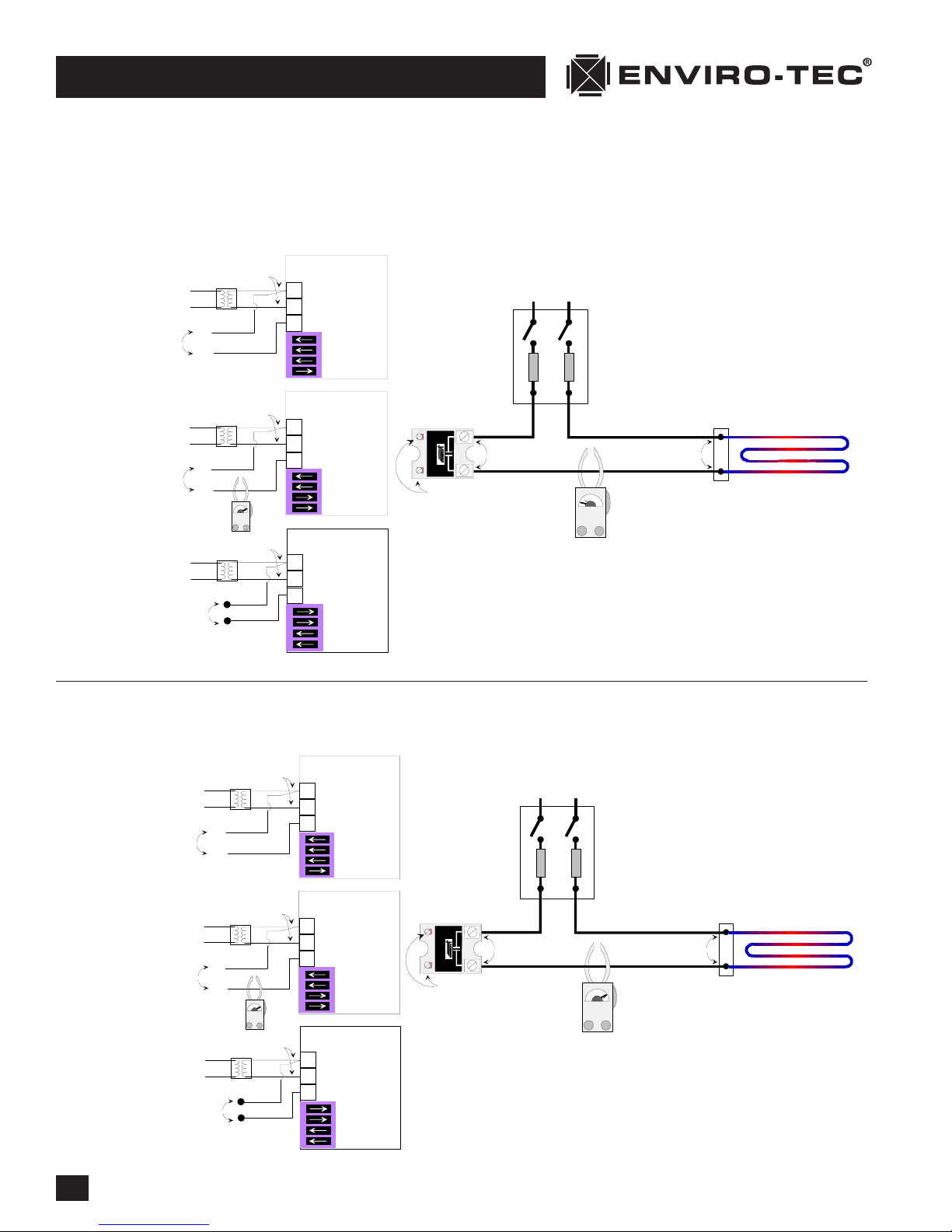
4. Apply Full Off Input per table above. If the unit is three phase, verify that the LED on the SSR (solid state
relay) is off. If the unit is single phase, measure voltage between P4 and P6 and verify 0.3 VDC + or - 0.3
VDC. Replace the interface circuit board if the voltage is higher than specified, or the LED is on.
5. Apply Full On Input per table above. If the unit is three phase, verify that the LED on the SSR (solid state
relay) is on. If the unit is single phase, measure voltage between P4 and P6 and verify between 3 and 5
VDC.
6. If the module provided is an ETPHCC or ETPHCC1, go to step 7. Apply “Pulse” Input per table above. If
the unit is three phase, verify that the LED on the SSR (solid state relay) is flashing at an interval of about
one second. If the unit is single phase, the voltage between P4 and P6 of the interface board should vary
between the Full Off and Full On voltages in steps 4 and 5 in intervals of about one second. NOTE: Some
voltmeters will not respond this quickly, so the value of the voltages may not appear to be correct; how-
ever, if the voltage appears to be changing at regular intervals, it may be assumed that this function is
operating properly. This completes the low voltage portion of the unit test. Go to step 8.
7. For the ETPHCC or ETPHCC1, the associated consignment controller must be directed to output a 50% On
pulse width modulation signal. For three phase, verify that the LED is pulsing at regular intervals. The rate
of the pulse is based on the output from the consignment controller. If the unit is single phase, the DC
voltage between P4 and P6 of the interface board should vary between the full Off and full On voltages in
steps 4 and 5. NOTE: Some voltmeters will not respond this quickly, so the value of the voltages may not
appear to be correct; however, if the voltage appears to be changing at regular intervals, it may be
assumed that this function is operating properly.
8. If the heater always remains energized when power is applied, remove the wire from P4 of the interface
circuit board. If the heat remains on, there is a wiring error or the SSR is defective. CAUTION: Remove
Power From the Unit Before Proceeding With the Next Step.
9. If the heater is always de-energized when power is applied, remove the line and load connections to the
proportional heat control and temporarily tie them together. If the system is a three phase arrangement,
do the phases one at a time. (NOTE: Always remove power from the unit before moving to the next phase).
Make sure there is no danger of the temporary connection shorting to another component or the chassis.
Briefly reapply power. If the section of heat under test now energizes, the SSR is defective. If heater still
will not energize, one of the heater safety devices (limits, safety contactor or airflow switch) or elements
is defective.
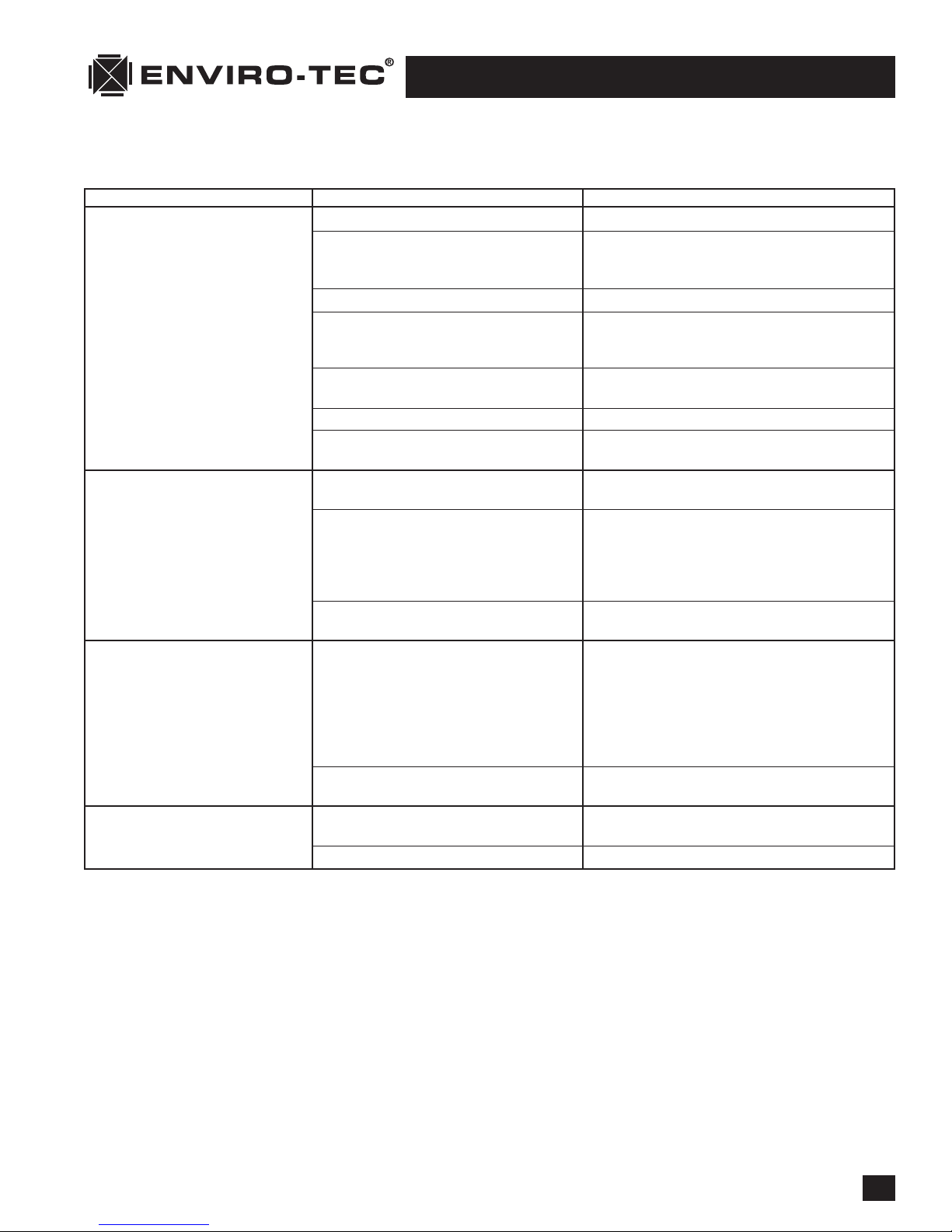
PROPORTIONAL HEAT CONTROL (SSR) TROUBLESHOOTING GUIDE
| ENVIRO-TEC HEATERS |