
ENVILINK T4000 Manuel utilisateur
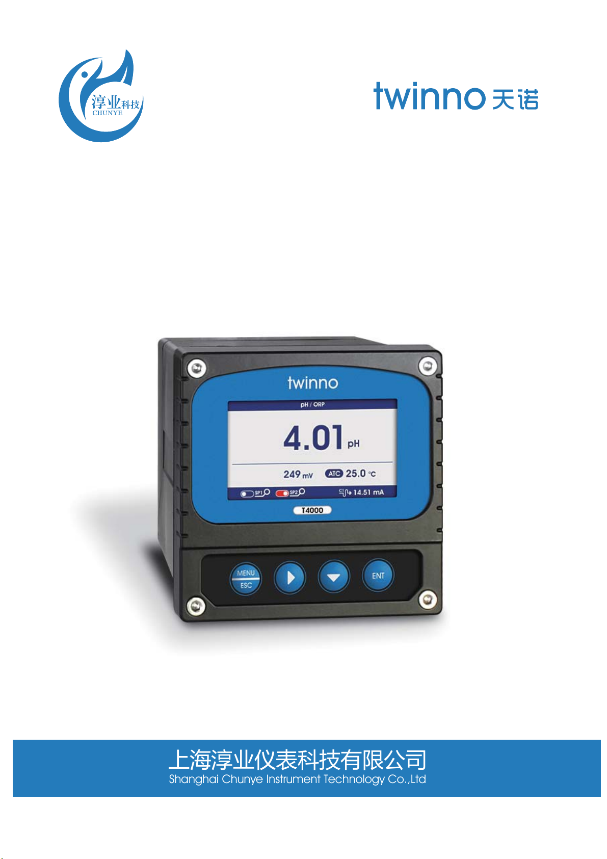
T4000 pH/ORP Online Analyzer
Operation Manual
上海淳业仪表科技有限公司
Shanghai Chunye Instrument Technology Co.,Ltd

Features
The instrument is equipped with different types of pH or ORP sensors. Widely used in power
plants, petrochemical industry, metallurgical electronics, mining, paper industry,
biological fermentation engineering, medicine, food and beverage, environmental
protection water treatment, aquaculture, modern agricultural planting and other
industries. The pH (acidity and alkalinity) value, ORP (redox potential) value and
temperature value of water solution were continuously monitored and controlled.
ӪColor LCD display
ӪIntelligent menu operation
ӪMultiple automatic calibration
ӪDifferential signal measurement mode, stable and reliable
ӪManual and automatic temperature compensation
ӪTwo relay control switches
ӪHigh & low alarm and hysteresis control
Ӫ4-20mA & RS485,Multiple output modes
ӪMulti parameter display simultaneously shows – pH/ORP, Temp, current,etc.
ӪPassword protection to prevent misoperation by non-staff.
Preface
Thank you for your support. Please read this manual carefully before use.The correct use
will maximize the performance and advantages of the product, and bring you a good
experience.
When receiving the instrument, please open the package carefully, check whether the
instrument and accessories are damaged by transportation and whether the accessories
are complete. If any abnormalities are found, please contact our after-sales service
department or regional customer service center, and keep the package for return
processing.
This instrument is an analytical measurement and control instrument with highly
precision.Only skilled,trained or authorized person should carry out installation, setup and
operation of the instrument.Ensure that the power cable is physically separated from the
power supply when connection or repair.Once the safety problem occurs, make sure that
the power to the instrument is off and disconnected.
For example, it may insecurity when the following situations occur:
1) Apparent damage to the analyzer
2) The analyzer does not work properly or provides specified measurements.
3)The analyzer has been stored for a long time in an environment where the temperature
exceeds 70 ˫.
The analyzer must be installed by professionals in accordance with relevant local
specifications, and instructions are included in the operation manual.
Comply with the technical specifications and input requirements of the analyzer.
1

Technical Specifications
Measuring range
Unit
Resolution
Basic error
Temperature
Temperature resolution
Temperature accuracy
Temperature compensation
Temperature compensation
Stability
Current outputs
Communication output
Two relay control contacts
Optional power supply
Working conditions
Working temperature
Relative humidity
Waterproof rating
Weight
Dimensions
Installation opening size
Installation methods
pH:-2~16pH; ORP:-1999~+1999mV
pH,mV
pH:0.01pH; ORP:1mV
pH:±0.02pH;ORP:±2mV;
0~150.0˫(Depend on the Sensor)
0.1˫
±0.3˫
0~150.0˫
Manual or automatic
pH:≤0.02pH/24h;ORP: ≤2mV/24h
Two :4~20mA,20~4mA,0~20mA
RS485 MODBUS RTU
Two:3A 250VAC,3A 30VDC
85~265VAC,9~36VDC,power consumption≤3W
No strong magnetic field interference except the geomagnetic field.
-10~60˫
≤90%
IP65
0.6kg
98×98×130mm
93×93mm
Panel & wall mounted
2
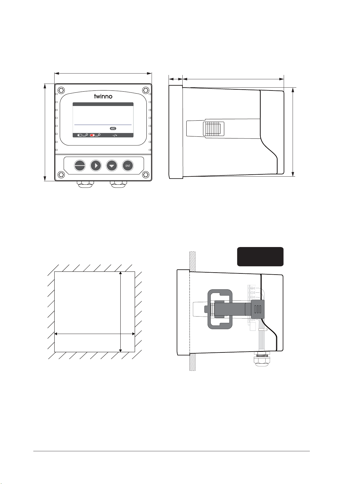
Instrument installation
Instrument dimensions Instrument dimensions(Side view)
Insert the instrument into the square hole
and fix it with the collocated clip.
Insert mounting hole size
Embedded installation
93 mm
93 mm
(± 0.5 mm)
(± 0.5 mm)
3
92.5 mm
10 mm
120 mm
98 mm
98 mm
MENU
ESC
pH
14.51 mA
C1
SP1 SP2
14.001
25.0
°C
pH
T4000
Installation of back
cover with
waterproofing seal
4
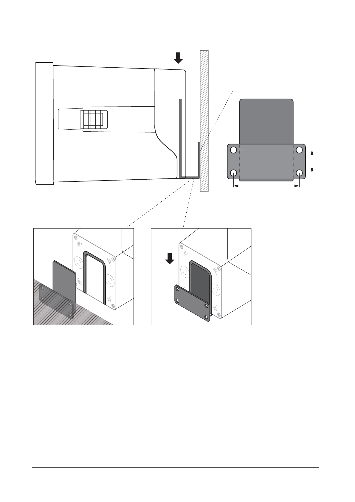
53 mm
18.4 mm
ħ5mm
a. Fixed bracket (M4 screw) is
installed on the wall first.
b. Insert the instrument into the
fixture along the chute
Fixture Dimension
Wall mounting
Fixed bracket (M4 screw) is
installed on the wall first.
Insert the instrument into the
fixture along the chute
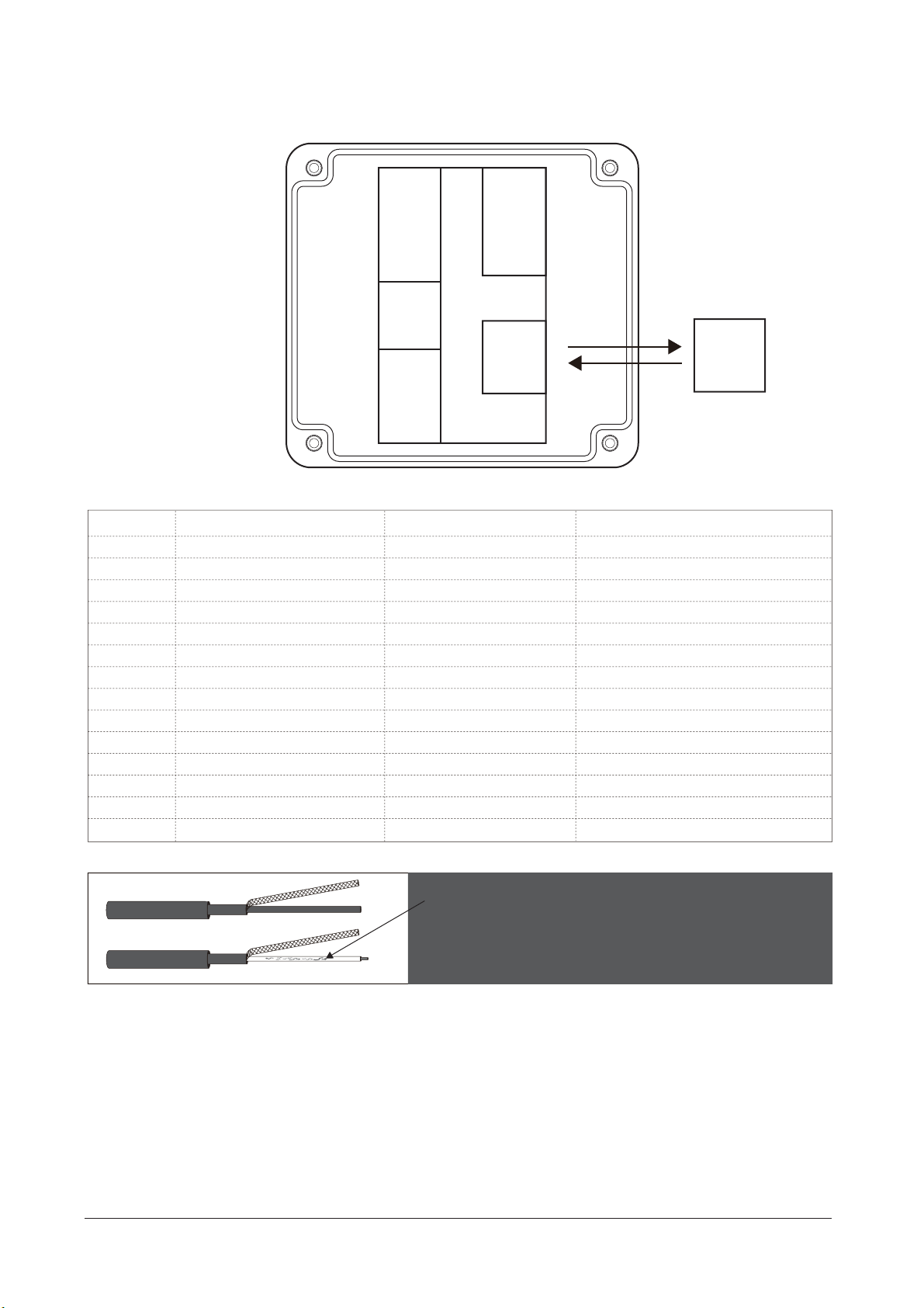
Instrument connection
5
Tip: if the user needs to lengthen or shorten the cable, please
remove the black conductive skin outside the transparent wire
to prevent short circuit between the black conductive skin and
the reference end of the electrode.Multimeter can be used to
check, please use special cable for pH connection.
Electrical connection
Connection between instrument and pH or ORP sensors: Connection of power supply, output
signal, relay contacts and instrument baseplate. The cable length of sensors is usually 5-10
meters. There are labeled inserts at the end of the cable, which can be inserted into the terminal
with the same digital symbols on the instrument roof and tightened.
Terminal
N/C
N/C
Temp
Temp
Input
Ref
N/C
N/C
N/C
Cur 1+
Com -
Cur 2+
RS485 B
RS485 A
N/C
N/C
Temp
Temp
Input
Ref
N/C
N/C
N/C
Cur 1+
Com -
Cur 2+
RS485 B
RS485 A
NO 1
COM 1
NC 1
NO 2
COM 2
NC 2
Pow DC+
(9~36V)
Pow DC-
Pow PE
Function
No connection
Temperature sensor
Temperature sensor
Measurment
Reference
Current output 1+
Current output common terminal
Current output 2+
Communication
Communication
Function
High set relay working position
Alarm relay common
High set relay resting position
Low set relay working position
Alarm relay common
Low set relay resting position
DC power +(9-36V)
DC power -
Earth wire
Live wire
Neutral wire
Earth wire
Terminal
NO 1
COM 1
NC 1
NO 2
COM 2
NC 2
Pow DC+ (9~36V)
Pow DC-
Pow PE
Pow ACL (85~265V)
Pow AC N
Pow PE
Pow ACL
(85~265V)
Pow AC N
Pow PE
pH/ORP
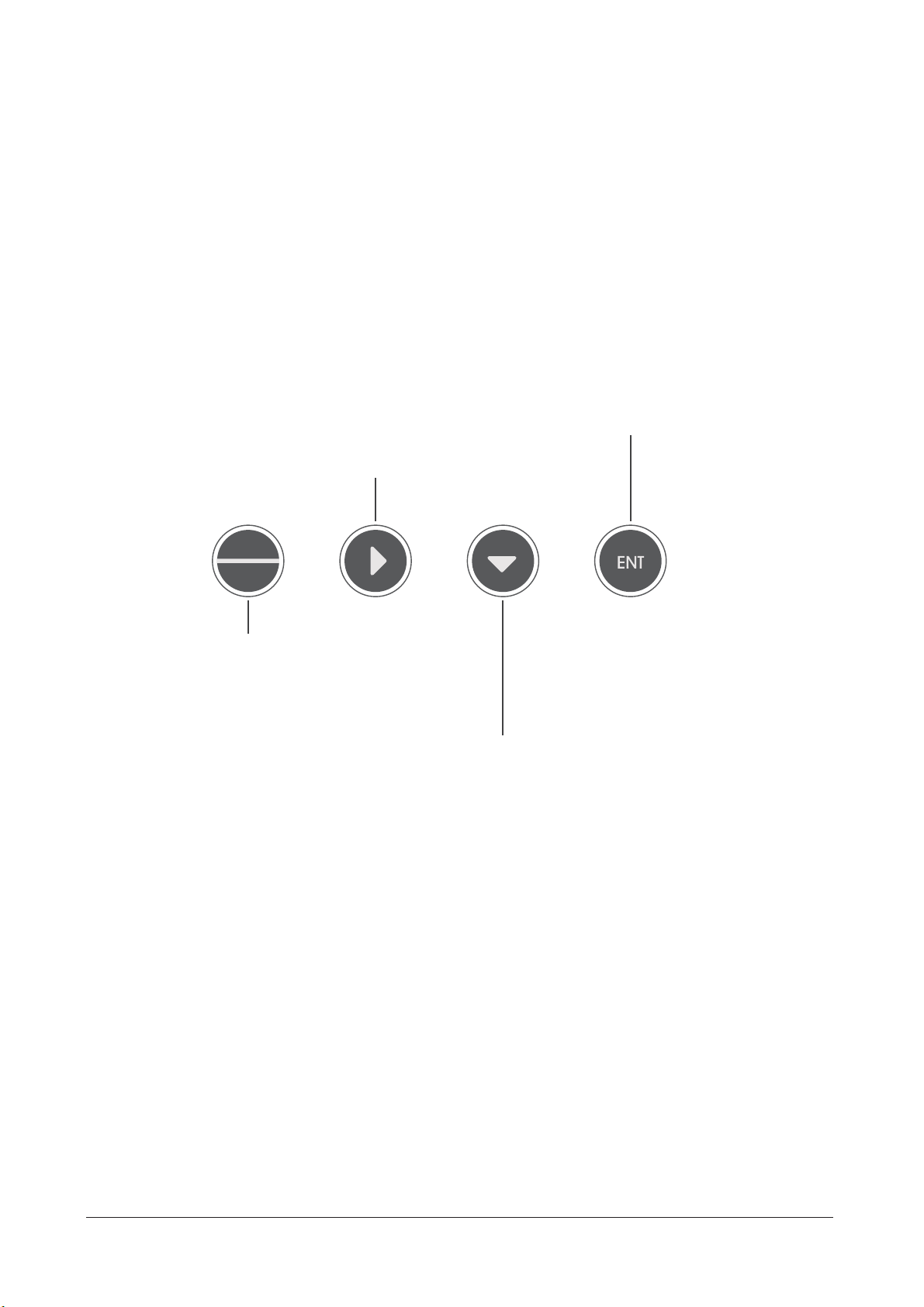
Keypad descriptions
Keypad operation tips:
Short Press: Short Press means to release the key immediately after pressing. ((Default to
short presses if not indicated below)
Long Press: Long Press is to press the button for 3 seconds and then release it.
Press and hold: Press and hold means to press the button, and accelerate after a certain
time until the data is adjusted to the user's required value before releasing the button.
Confirmation options
Enter menu setting mode
Return to previous menu
Long press to return the measurements screen
Menu setting mode: press this key to loop down the menu options
Value input mode: current bit value change (loop)
In measurement mode, long press this button to set parameters for browsing
Press this key to move menu options left (circle)
6
MENU
ESC
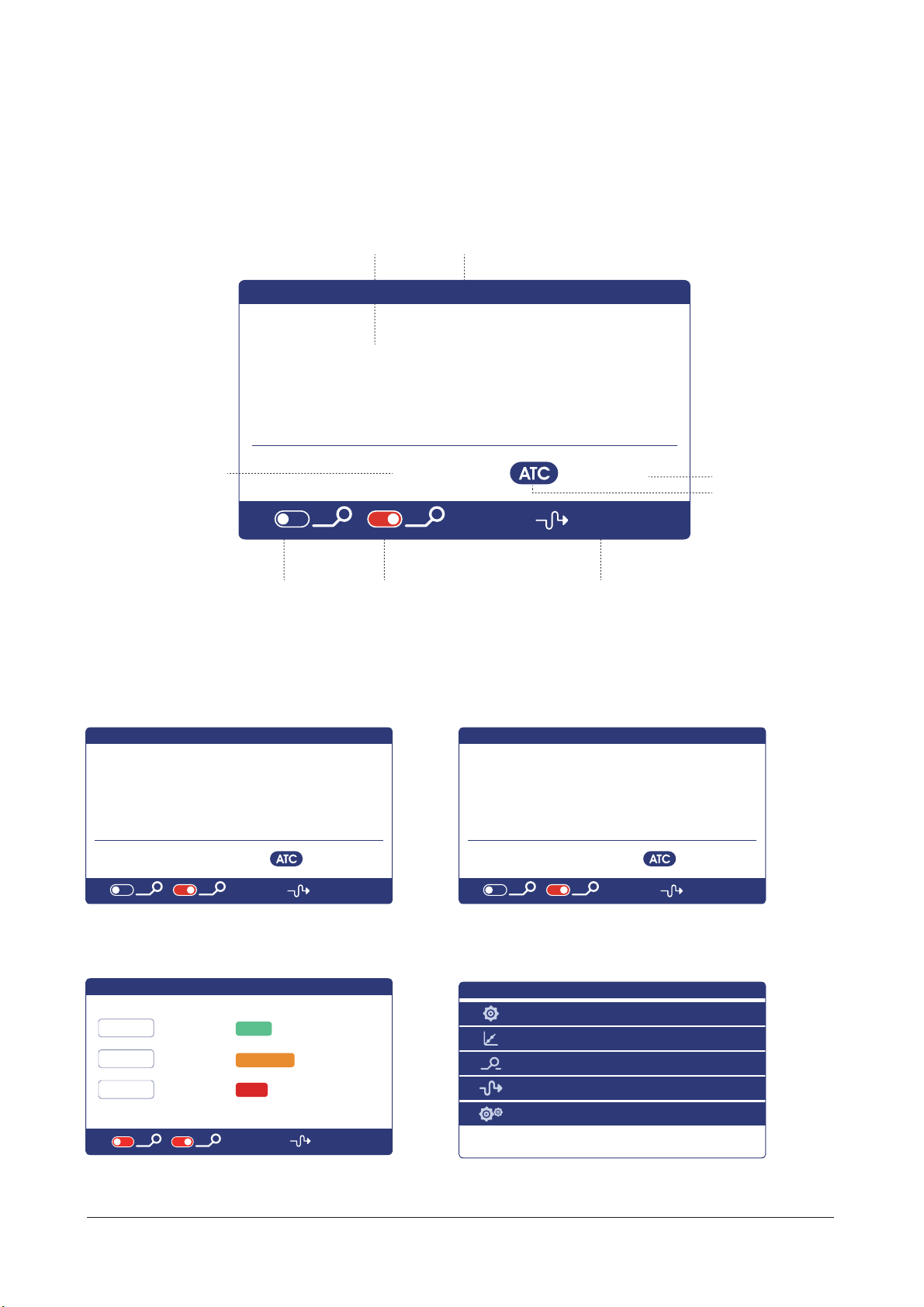
Relay 1
[blue is off
and red is on]
Instrument type
Display descriptions
All pipe connections and electrical connections should be checked before use. After the power is
switched on, the meter will display as follows.
Setting mode
pH measurement mode ORP measurement mode
Calibration mode
pH value+ Unit
Relay 2
[blue is off
and red is on]
Current 1
Current 2
Switch display
Automatic
temp. comp.
Temp. + Unit
Voltage value
corresponding
to pH
7
7.00
4.01
10.01
-5 mV
170 mV
-25 mV
98 %
Done
Calibrating
Error
offset:
Slope:
pH / ORP
14.51 mA
C1
SP1 SP2
pH / ORP
14.51 mA
C1
SP1 SP2
14.01 pH
25.0 °C249 mV
pH / ORP
14.51 mA
C1
SP1 SP2
14.01 pH
25.0 °C249 mV
pH / ORP
14.51 mA
C1
SP1 SP2
235 mV
25.0 °C
Configure
Calibration
Set Points
Output
System
pH / ORP

Type
Unit
Temperature Sensor
Temperature Offset
Temperature Input
Temperature Unit
USA:7.00,4.01,10.01
NIST:6.86,4.01,9.18
ORP Standard Sulution
Field Calibration
Offset Adjustment
Slope Adjustment
Correction
Status
High/Low Setpoint
Limit Value
Hysteresis
Status
High/Low Setpoint
Limit Value
Hysteresis
Sensor
Temperature
Standard
Calibration
Field
Calibration
Relay 1
Relay 2
Configure
Calibration
Alarm
PH
ORP
pH
mV
NTC2.252 kΩ
NTC10 kΩ
Pt100
Pt1000
0.0000
Automatic
Manual
°C
°F
Automatic identification,calibrate 7.00 first
Automatic identification,calibrate 6.86 first
235mV(Default)
Offset
Slope
ON
OFF
High Alarm
Low Alarm
ON
OFF
High Alarm
Low Alarm
8
Menu structure
If the monitor prompts you to enter the calibration security password, press the【▼】 key or 【Ӝ】key to
set the calibration security password, and then press the 【ENT】key to confirm the calibration security
password.No initial password here,please enter directly by press【ENT】key.
The following is the menu structure of this instrument,pressսMENUվkey to enter menu
setting mode:

Channel
Output Option
Upper Limit
Lower Limit
Channel
Output Option
Upper Limit
Lower Limit
Baud Rate
Parity Check
Stop Bit
Network Node
Chinese
English
Display Speed
Backlight
Soft Version
Password Settings
Serial Number
1.No
2.Yes
Current 1 4mA
Current 1 20mA
Current 2 4mA
Current 2 20mA
Relay 1
Relay 2
Current 1
Current 2
RS485
Language
Display
Soft Version
Factory Default
Terminal
Current Tuning
Relay Test
Output
System
Main
Temperature
4-20mA
0-20mA
20-4mA
Main
Temperature
4-20mA
0-20mA
20-4mA
4800BPS
9600BPS
19200BPS
None
Odd
Even
1 Bit
2 Bit
001+
Low
Standard
Medium
High
Saving
Bright
T4000C V1.0
0000
9
(The positive and negative
ends of the ammeter are
connected to the current 1
or current 2 output terminals
of the instrument
respectively, pressսӞվkey
to adjust the current to 4
mA or 20mA ,pressսENTվkey
to confirm.)
(Select two relays and hear
the relay switch twice
sounds,indicate the relay is
normal.)
Table des matières
Manuels Instrument de mesure populaires d'autres marques


Endress+Hauser
Endress+Hauser Proline Promag 50 Caractéristiques techniques

Siemens
Siemens SITRANS F Coriolis FCT030 Manuel de la liste des pièces

KLINGER
KLINGER CMF V Series Manuel utilisateur

EXFO
EXFO FTB-2 Manuel d'exploitation et d'entretien

Keysight
Keysight M8290A Manuel utilisateur

ADTEK
ADTEK MW-5 Manuel utilisateur