Endress+Hauser RIA15 Manuel utilisateur

Products Solutions Services
Operating Instructions
RIA15
Loop-powered 4 to 20 mA process display unit
with HART® communication
BA01170K/09/EN/05.15
71300896
Valid as of FW version:
01.04.xx


Table of contents
Endress+Hauser 3
Table of contents
1 Document information .............. 4
1.1 Document function ..................... 4
1.2 Document conventions ................... 4
1.3 Registered trademarks ................... 6
2 Safety instructions .................. 7
2.1 Requirements for the personnel ............ 7
2.2 Designated use ........................ 7
2.3 Workplace safety ....................... 7
2.4 Operational safety ...................... 7
2.5 Product safety ......................... 8
3 Product description ................. 9
3.1 Function ............................. 9
3.2 Operating modes ....................... 9
3.3 Input channels ........................ 12
4 Identification ..................... 13
4.1 Nameplate ........................... 13
4.2 Scope of delivery ...................... 13
4.3 Certificates and approvals ............... 13
4.4 HART® protocol certification ............. 14
5 Installation ....................... 15
5.1 Incoming acceptance, transport, storage ..... 15
5.2 Installation conditions .................. 15
5.3 Installation instructions ................. 15
5.4 Post-installation check .................. 19
6 Wiring ............................ 21
6.1 Quick wiring guide ..................... 21
6.2 Connection in 4 to 20 mA mode ........... 22
6.3 Connection in HART mode ............... 22
6.4 Wiring with switchable backlighting ........ 27
6.5 Inserting the cable, field housing .......... 29
6.6 Shielding and grounding ................ 29
6.7 Connecting to functional grounding ........ 30
6.8 Degree of protection ................... 31
6.9 Post-connection check .................. 31
7 Operation ......................... 32
7.1 Operating functions .................... 32
8 Commissioning .................... 34
8.1 Post-installation check and switching on the
device .............................. 34
8.2 Operating matrix ...................... 34
8.3 Operating matrix in conjunction with the
Micropilot FMR20 ..................... 39
9 Troubleshooting .................. 41
9.1 Error limits as per NAMUR NE 43 ......... 41
9.2 Diagnostic messages ................... 41
9.3 Spare parts .......................... 44
9.4 Software history and overview of
compatibility ......................... 44
10 Maintenance ...................... 46
11 Return ............................ 47
12 Disposal .......................... 48
13 Accessories ....................... 49
13.1 Device-specific accessories ............... 49
13.2 Service-specific accessories ............... 50
14 Technical data .................... 51
15 HART® communication ............ 55
15.1 HART® protocol command classes .......... 55
15.2 HART® commands used ................. 56
15.3 Field device status ..................... 56
15.4 Supported units ....................... 57
15.5 HART® protocol connection types .......... 61
15.6 Device variables for multivariable devices .... 62
Index .................................. 63

Document information RIA15
4 Endress+Hauser
1 Document information
1.1 Document function
These Operating Instructions contain all the information that is required in various phases
of the life cycle of the device: from product identification, incoming acceptance and
storage, to mounting, connection, operation and commissioning through to
troubleshooting, maintenance and disposal.
1.2 Document conventions
1.2.1 Safety symbols
Symbol Meaning
DANGER
DANGER!
This symbol alerts you to a dangerous situation. Failure to avoid this situation will result in
serious or fatal injury.
WARNING
WARNING!
This symbol alerts you to a dangerous situation. Failure to avoid this situation can result in
serious or fatal injury.
CAUTION
CAUTION!
This symbol alerts you to a dangerous situation. Failure to avoid this situation can result in
minor or medium injury.
NOTICE
NOTE!
This symbol contains information on procedures and other facts which do not result in
personal injury.
1.2.2 Electrical symbols
Symbol Meaning
A0011197
Direct current
A terminal to which DC voltage is applied or through which direct current flows.
A0011198
Alternating current
A terminal to which alternating voltage is applied or through which alternating current flows.
A0017381
Direct current and alternating current
• A terminal to which alternating voltage or DC voltage is applied.
• A terminal through which alternating current or direct current flows.
A0011200
Ground connection
A grounded terminal which, as far as the operator is concerned, is grounded via a grounding
system.
A0011199
Protective ground connection
A terminal which must be connected to ground prior to establishing any other connections.
A0011201
Equipotential connection
A connection that has to be connected to the plant grounding system: This may be a potential
equalization line or a star grounding system depending on national or company codes of practice.
A0012751
ESD - Electrostatic discharge
Protect the terminals against electrostatic discharge. Failure to comply with this instruction can
result in the destruction of parts or malffunction of the electronics.

RIA15 Document information
Endress+Hauser 5
1.2.3 Symbols for certain types of information
Symbol Meaning
Permitted
Procedures, processes or actions that are permitted.
Preferred
Procedures, processes or actions that are preferred.
Forbidden
Procedures, processes or actions that are forbidden.
Tip
Indicates additional information.
Reference to documentation
Reference to page
Reference to graphic
,…
,
Series of steps
Result of a step
Help in the event of a problem
Visual inspection
1.2.4 Symbols in graphics
Symbol Meaning
1, 2, 3,... Item numbers
,…
,
Series of steps
A, B, C, ... Views
A-A, B-B, C-C, ... Sections
A0013441
Flow direction
-
A0011187
Hazardous area
Indicates a hazardous area.
.
A0011188
Safe area (non-hazardous area)
Indicates a non-hazardous area.
1.2.5 Tool symbols
Symbol Meaning
A0011220
Flat blade screwdriver
A0011221
Allen key
A0011222
Open-ended wrench
A0013442
Torx screwdriver

Document information RIA15
6 Endress+Hauser
1.3 Registered trademarks
HART®
Registered trademark of the HART® Communication Foundation

RIA15 Safety instructions
Endress+Hauser 7
2 Safety instructions
2.1 Requirements for the personnel
The personnel for installation, commissioning, diagnostics and maintenance must fulfill
the following requirements:
‣Trained, qualified specialists must have a relevant qualification for this specific function
and task
‣Are authorized by the plant owner/operator
‣Are familiar with federal/national regulations
‣Before beginning work, the specialist staff must have read and understood the
instructions in the Operating Instructions and supplementary documentation as well as
in the certificates (depending on the application)
‣Following instructions and basic conditions
The operating personnel must fulfill the following requirements:
‣Being instructed and authorized according to the requirements of the task by the
facility's owner-operator
‣Following the instructions in these Operating Instructions
2.2 Designated use
The process display unit displays analog process variables or HART ® process variables on
its screen.
The device is powered via the 4 to 20 mA current loop and does not require an additional
power supply.
• The manufacturer accepts no liability for damages resulting from incorrect use or use
other than that designated. It is not permitted to convert or modify the device in any
way.
• Panel-mounted device
The device is designed for installation in a panel and must only be operated in an
installed state.
• Field device:
The device is designed for installation in the field.
• The device may only be operated under the permitted ambient conditions → 52.
2.3 Workplace safety
For work on and with the device:
‣Wear the required personal protective equipment according to federal/national
regulations.
2.4 Operational safety
Risk of injury.
‣Operate the device in proper technical condition and fail-safe condition only.
‣The operator is responsible for interference-free operation of the device.
Conversions to the device
Unauthorized modifications to the device are not permitted and can lead to unforeseeable
dangers.
‣If, despite this, modifications are required, consult with Endress+Hauser.

Safety instructions RIA15
8 Endress+Hauser
Repair
To ensure continued operational safety and reliability,
‣Carry out repairs on the device only if they are expressly permitted.
‣Observe federal/national regulations pertaining to repair of an electrical device.
‣Use original spare parts and accessories from Endress+Hauser only.
Environmental requirements
If a plastic transmitter housing is permanently exposed to certain steam and air mixtures,
this can damage the housing.
‣If you are unsure, please contact your Endress+Hauser Sales Center for clarification.
‣If used in an approval-related area, observe the information on the nameplate.
2.5 Product safety
This measuring device is designed in accordance with good engineering practice to meet
state-of-the-art safety requirements, has been tested, and left the factory in a condition in
which it is safe to operate.
It meets general safety standards and legal requirements. It also complies with the EC
directives listed in the device-specific EC Declaration of Conformity. Endress+Hauser
confirms this by affixing the CE mark to the device.

RIA15 Product description
Endress+Hauser 9
3 Product description
3.1 Function
Process display unit RIA15 is integrated in the 4 to 20 mA/HART® loop and transmits the
measuring signal in digital form. The process display unit does not require an external
power supply. It is powered directly from the current loop.
In connection with the radar level sensor Micropilot FMR20, the RIA15 can be used to
make the basic settings for the Micropilot FMR20. As a prerequisite the RIA15 must be
ordered with the respective option for the FMR20 basic setting.
The device meets the requirements of the HART® Communication Protocol Specifications
and can be used with devices with HART® Revision ≥ 5.0.
3.2 Operating modes
The process display unit can be used in two different operating modes:
4 to 20 mA mode:
In this operating mode, the process display unit is incorporated into the 4 to 20 mA
current loop and measures the transmitted current. The variable calculated based on the
current value and range limits is displayed in digital form on the 5-digit LCD. In addition,
the associated unit and a bar graph can be displayed.
HART mode:
The device functions as a display unit even when operating with a HART® sensor/actuator.
In this case, the display is also powered from the current loop.
The process display unit can choose to function as a primary master or secondary master
(default) in the HART® loop. When it functions as a master, the device can read process
values from the measuring device and display them. HART® communication operates on
the principle of master/slave. As a general rule, the sensor/actuator is a slave and only
transmits information if a request has been made by the master.
A HART® loop can have a maximum of two HART® masters at any one time. A distinction
is made between primary (e.g. the control system) and secondary master (e.g. handheld
terminal for on-site operation of the measuring devices) for these HART® masters. The
two masters in the loop/in the network cannot be masters of the same type, e.g. they
cannot be two "secondary masters".
If a third HART® master is added to the network, one of the other masters must be
disabled; otherwise a collision occurs in the network.
If the process display unit is operating as "secondary master" and another "secondary
master", e.g. a handheld device, is added to the network, the device interrupts HART®
communication as soon as it detects that there is another "secondary master". The display
alternates between error message C970 "Multi master collision" and "- - -". A measured
value is not displayed in this case. The device leaves the HART® loop for 30 seconds and
tries to re-establish HART® communication once again. Once the additional "secondary
master" is removed from the network, the device continues communication and displays
the measured values of the sensor/actuator once more.
Please note that if two process display units are to be used in a multidrop connection,
one device must be configured as "primary master" and the other as "secondary master"
to prevent a master collision.
In HART mode, the process display unit can show up to four device variables of a
multivariable measuring device. These variables are referred to as the Primary Variable
(PV), Secondary Variable (SV), Tertiary Variable (TV) and Quaternary Variable (QV). These
variables are placeholders for measured values that can be called up using HART®
communication.
Product description RIA15
10 Endress+Hauser
For a flowmeter, such as the Promass, these four values can be as follows:
• Primary process variable (PV) →Mass flow
• Secondary process variable (SV) → Totalizer 1
• Third process variable (TV) → Density
• Fourth process variable (QV) → Temperature
The HART® section at the end of these Operating Instructions provides examples of these
four device variables for multivariable measuring devices → 62.
Please refer to the Operating Instructions for each device for details on the variables
that are set as default on the sensor/actuator and how they can be changed.
The process display unit can show each of these values. The individual values must be
activated in the SETUP – HART1 to HART4 menu for this purpose. The individual
parameters are assigned to fixed process variables in the device in this case:
HART1 = PV
HART2 = SV
HART3 = TV
HART4 = QV
For example, if the PV and TV are to be displayed on the process display unit, HART1 and
HART3 must be activated.
The values can either be shown alternately on the process display unit or one value is
displayed continuously and the other values are only shown by pressing '+' or '–'. The
switching time can be configured in the "EXPRT" – "SYSTM" – "TOGTM" menu.
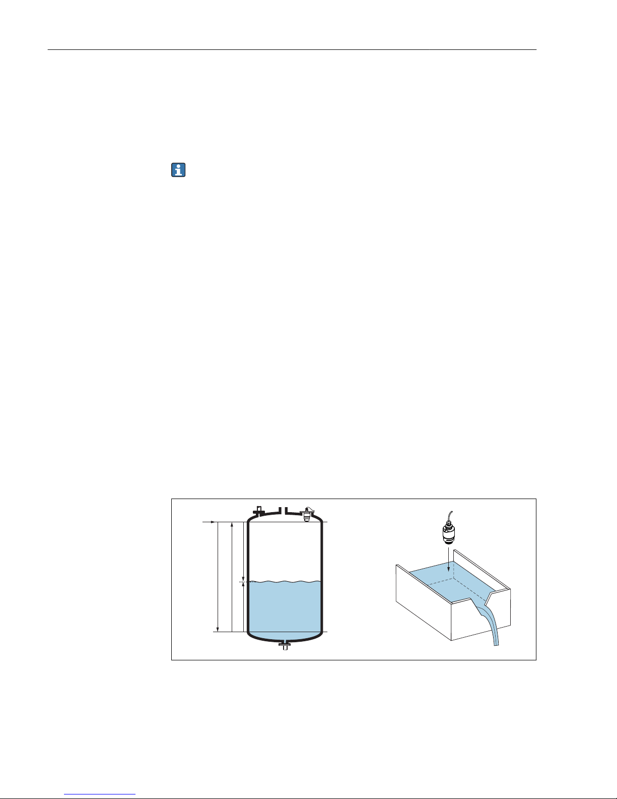
3.2.1 RIA15 as a remote display and for operation of the Micropilot
FMR20
The Micropilot is a "downward-looking" measuring system, operating based on the time-of-
flight method (ToF). It measures the distance from the reference point (process
connection) to the product surface. Radar impulses are emitted by an antenna, reflected
off the product surface and received again by the radar system.
The FMR20 can be adjusted under the "SETUP → LEVEL" menu (see operating matrix). The
measured value displayed corresponds to the distance measured or, if linearization is
enabled, to a percentage value.
D
Q
R
100%
0%
D
L
F
E
A0028409
1 Setup parameters of the Micropilot
E Empty calibration (= zero)
F Full calibration (= span)
D Measured distance
L Level (L = E - D)
Q Flow rate at measuring weirs or channels (calculated from the level using linearization)
Autres manuels pour RIA15
6
Table des matières
Autres manuels Endress+Hauser Écran tactile


Manuels Écran tactile populaires d'autres marques


IBASE Technology
IBASE Technology ASTUT-152-RE1S Manuel utilisateur

YASKAWA
YASKAWA TP 610C Manuel utilisateur

B&R
B&R Power Panel C Series Manuel utilisateur

Beijer Electronics
Beijer Electronics X2 control Manuel utilisateur

AXIOMTEK
AXIOMTEK GOT321W-521 Manuel utilisateur

TRIDONIC.ATCO
TRIDONIC.ATCO x-touchBOX Manuel utilisateur


