Elife SR Series Manuel utilisateur
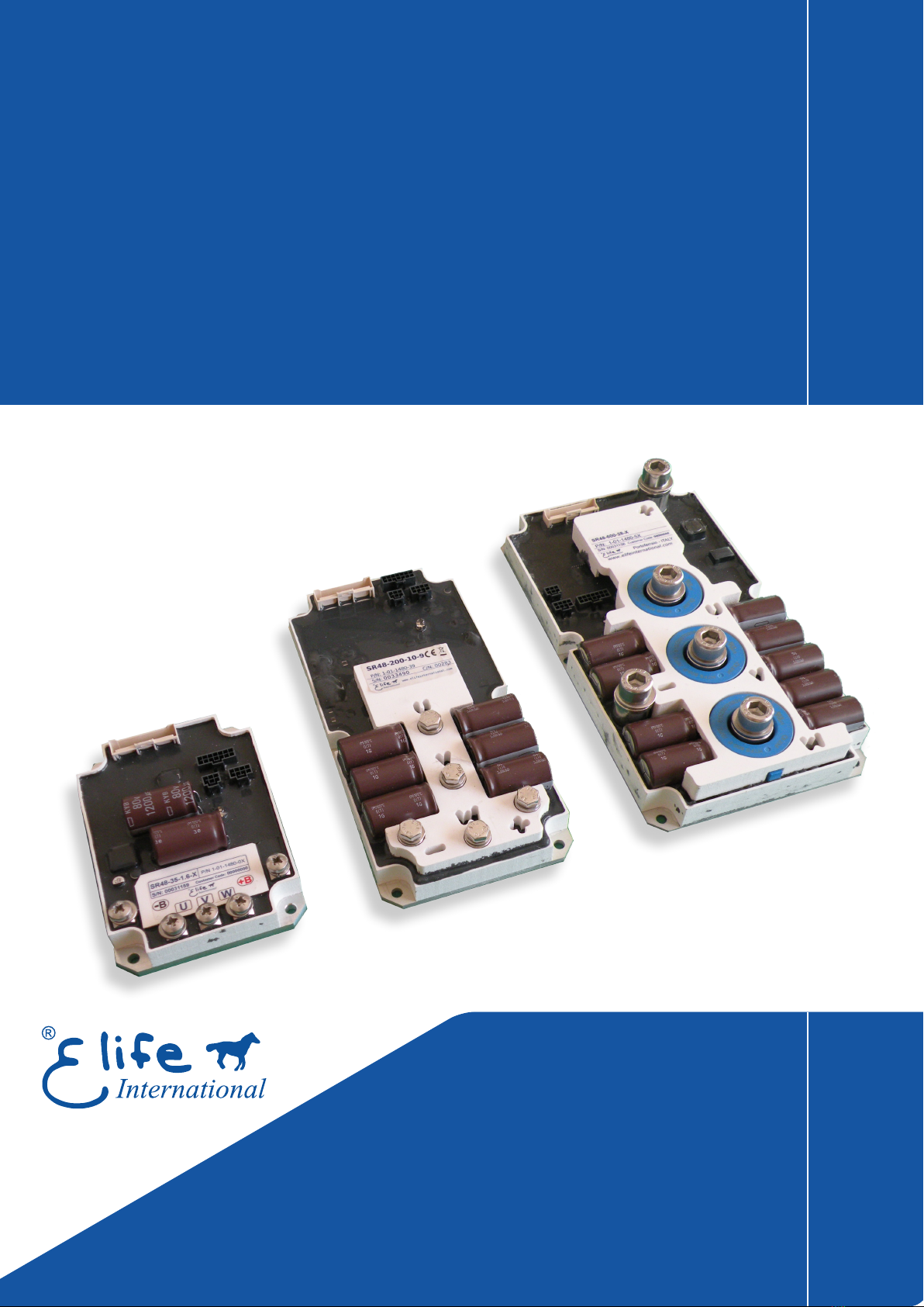
Low Profile Drive
Size 1 - Size 2 - Size 3
Elife-Drive SR Series
Application
Reference Manual

Elife International S.r.l.
Via del Giglio, 4 - 57037 Portoferraio - LI
Elba Island - Tuscany - Italy
Tel: +39 0565 944121
Fax: +39 0565 945726
email: [email protected]
This manual is copyrighted of Elife International. All rights are reserved. This manual must not be
copied in whole or in part, nor transferred to any other media or language, without express written
permission of Elife International.
Technical Manual Version: 1.0 r04.02
Release Data: 09 May 2021

Contents
1 Overview 1
2 Installation and Wiring 5
2.1 Mounting Elife-Drive on-board . . . . . . . . . . . . . . . . . . . . . 5
2.2 Connections................................ 7
2.2.1 High Power Connections . . . . . . . . . . . . . . . . . . . . . 8
2.2.2 Low Power Connections . . . . . . . . . . . . . . . . . . . . . 10
2.3 Standard Wiring Diagrams . . . . . . . . . . . . . . . . . . . . . . . . 15
2.3.1 StandaloneMode......................... 18
2.3.2 CANopen®Mode ......................... 21
2.3.3 RS232Mode ........................... 22
2.3.4 EVCarMode ........................... 23
2.3.5 EVBikeMode........................... 25
3 Monitoring Elife Drive 27
3.1 LEDDiagnostics.............................. 27
3.2 Telemetry - Monitoring and Setting of Data . . . . . . . . . . . . . . 28
3.2.1 MotorSetting........................... 29
3.2.2 FeedbackSetting ......................... 30
3.2.3 System Parameters . . . . . . . . . . . . . . . . . . . . . . . . 31
3.2.4 Configuration - Connection . . . . . . . . . . . . . . . . . . . 32
3.2.5 Configuration - Standalone . . . . . . . . . . . . . . . . . . . 33
3.2.6 Configuration - CANopen®.................... 34
3.2.7 Configuration - RS232 . . . . . . . . . . . . . . . . . . . . . . 35
3.2.8 Configuration - EV BIKE . . . . . . . . . . . . . . . . . . . . . 36
3.2.9 Configuration - EV CAR . . . . . . . . . . . . . . . . . . . . . 37
3.2.10IDDrive.............................. 38
3.2.11Adjustments............................ 39
3.2.12LogStatus............................. 40
i

List of Tables
2.1 Fuse size in accordance with the Elife-Drive SR Series . . . . . . . . . . 8
2.2 A summary table of high-power connections . . . . . . . . . . . . . . . 8
2.3 Elife-Drive SR I/O definitions for Standalone Traction Mode . . . . . 19
2.4 Elife-Drive SR I/O definitions for Standalone Steering Mode . . . . . 20
2.5 Elife-Drive I/O definitions for CANopen®Mode............. 21
2.6 Elife-Drive I/O definitions for RS232 Mode ............... 22
2.7 Elife-Drive SR I/O definitions for Ev Car Mode.............. 23
2.8 Elife-Drive SR I/O definitions for Ev Bike Mode ............. 25
ii

1
Overview
SR Elife-Drive
is the family of drivers designed to drive the various types of
low-voltage servomotors, specifically for use in battery powered devices.
The compact form was made possible thanks to the high efficiency of the design,
manufactured with state-of-art electronic components.
Elife-Drive is highly configurable, a wide range of programmable parameters allow
you to customize your system for your needs.
The main key features include:
•
Designed to drive from 12 V to 96 V Brushless, Brushed and AC ServoMotors.
•
The different types of feedback are supported:
Resolver
,SinCos,Hall Sensors,
Incremental Encoder,Fa-Coder,SSI,Sensorless.
•Advanced algorithms for predictive speed and torque control.
•
CANopen
®
modes of operation:
1
: Profile Velocity Mode, Torque Profile Mode,
Profile Position Mode, Homing Mode and Cycilic Sync Position Mode
•
Electromagnetic Holding Brake Output with DPR System (Dynamic Power
Reduction)
•Dedicated Safe Torque Off (STO) input
•Telemetry of the Internal functions
•
European Conformity
C
, and designed and tested in accordance with the
EMC
emission (EN 61000-6-4) and immunity (EN 61000-6-2) standards.
Elife-Drive is compliant with EN 60950-1 safety requirements.
1Elife International is a Member of CiA®- CAN in Automation
1

Specification:
Four Quadrant Regenerative Operation
Space Vector Modulation Technology
Sinusoidal and Trapezoidal Commutation Methods
Programmable Gain Setting
Fully Configurable Velocity and Position Limits
On-the-fly Mode and Gain Set Switching
Emergency Deceleration Ramp (Emergency) Input
Safe Torque Off (STO) Input
Programmable Input/Output:
Six Digital Inputs Single Ended
One 12-bit Analog Input 0÷10 V
Four Digital Outputs Singled Ended
One High Powered Brake Output
One Programmable 5 or 10V - 100mA Throttle Output
SIZE 1 NOMINAL BATTERY VOLTAGE - MAX MOTOR POWER
120x85x38 mm 12V - 400W 24V - 800W 48V - 1.6kW
PHASE CURRENT *10V ÷ 22V 16V ÷ 34V 28V ÷ 70V
up to 35 Arms SR12-35-040-x SR24-35-080-x SR48-35-1.6-x
up to 70 Arms SR12-70-040-x SR24-70-080-x SR48-70-1.6-x
SIZE 2 NOMINAL BATTERY VOLTAGE - MAX MOTOR POWER
195x95x32 mm 12V - 2.5kW 24V - 5kW 48V - 10kW 72V - 15kW
PHASE CURRENT *10V ÷ 22V 16V ÷ 34V 28V ÷ 75V 46V ÷ 100V
up to 100 Arms SR12-100-2.5-x SR24-100-5-x SR48-100-10-x SR72-100-15-x
up to 200 Arms SR12-200-2.5-x SR24-200-5-x SR48-200-10-x SR72-200-15-x
SIZE 3 NOMINAL BATTERY VOLTAGE - MAX MOTOR POWER
220x120x32 mm 12V - 7kW 24V - 14kW 48V - 28kW 72V - 43kW 96V - 56kW
PHASE CURRENT *10V ÷ 22V 16V ÷ 34V 28V ÷ 75V 46V ÷ 100V 65V to 150V
up to 400 Arms SR12-400-7-x SR24-400-14-x SR48-400-28-x SR72-400-43-x SR96-400-56-x
up to 600 Arms SR12-600-7-x SR24-600-14-x SR48-600-28-x SR72-600-43-x - - - - - -
* The value of the maximum continuous (60 min) RMS phase current is ensured with an appropriate heat sink.
2Chapter 1 Overview

Product Identification Label
Most of information about your Elife-Drive - such as serial number, model, customer
information, etc - can be found on a label located on the front of the Elife-Drive (see
figure below). Some of these information might be requested when you contact the
technical assistance.
Compliance with the EU regulatory requirement for electrical and electronic equipment.
When your Elife-Drive is no more usable, can’t be treated as generic garbage, but
must be disposed of at a collection point for recycling of electrical and electronic
equipment, in compliance with the
WEEE
regulation (Waste of Electrical and
Electronic Equipment).
3

4

2
Installation and Wiring
2.1 Mounting Elife-Drive on-board
The Elife-Drive can be mounted in any orientation, but you must choose a location
in order to keep the controller
clean
and
dry
, aways from sunlight, water and ice.
When you mount the Elife-Drive on-board you should
ensure an effective heat
dissipation between the Elife-Drive and the vehicle surface.
Elife-Drive has a LED light on the front of the device that visually explains what
the driver is doing (see Section 3.1), if you want it to be visible you should take
this into consideration before choosing the location where your Elife-Drive will be
mounted.
In order to ensure the proper functioning of the Elife-Drive you must keep the
controller clean and dry and ensure an effective heat exchange between the
Elife-Drive and the vehicle surface.
Warning
The installation must be performed with an adequate heat exchange between the
Elife-Drive and the surface on which it will be placed. In Figure 2.1 is shown
a suggested installation method in order to ensure an effective heat dissipation
between the Elife-Drive and the surface on which it will be placed.
A thermal grease should be used on the rear side of the Elife-Drive heatsink to
improve the heat exchange between Elife-Drive and the surface on which it
will be placed.
Tips and Advice
If the installation method shown in Figure 2.1 is not sufficient to ensure an effective
heat dissipation from the Elife-Drive, you should install a Fan Cooler or a Liquid
Cooler on your Elife-Drive.
5

Figure 2.1:
A recommended installation method in order to ensure an effective heat
dissipation between the Elife-Drive and the surface on which it will be placed. A thermal
grease should be used between the Elife-Drive and the surface on which it will be placed.
6Chapter 2 Installation and Wiring
Ce manuel convient aux modèles suivants
23
Table des matières
Manuels Entraînement CC populaires d'autres marques

Vincent Associates
Vincent Associates UNIBLITZ ED12DSS Manuel utilisateur

EKSMA OPTICS
EKSMA OPTICS DQ-100-4 Manuel de la liste des pièces

Chamberlain Garog
Chamberlain Garog D Series Manuel utilisateur

Parker
Parker PDS Series Manuel utilisateur

Festo
Festo DGC G Series Guide de configuration

Binks
Binks QS-5012-1-CE Manuel utilisateur


