Elektor 19883 Manuel utilisateur

●1
32 pages
instructions
2 MHz LCR Meter Kit
Assembly & Calibration
Step-by-step instructions from
First Start-up to Final Adjustments
Jean-Jacques Aubry
V3.2

2 MHz LCR Meter Kit AU2019 Assembly Manual
●2
●3
2 MHz LCR Meter Kit
AU2019
Assembly and Calibration Manual
V3.2 - Last update 2021/10/25
This manual, initially printed and included in the kit, is also available as
a downloadable PDF. Corrections are made as we receive feedback. We
invite you to check that you are in possession of the updated version
of this essential document which you can find at the following address:
www.elektor.com/19883
Note: Small differences may exist between the kit as received compared to the
version pictured. These differences are inconsequential.
2 MHz LCR Meter Kit AU2019 Assembly Manual
●4
Main Technical Specifications
Display - Parameter values (principal and secondary)
- Equivalent circuit: series or parallel
- Frequency
- |Z|
- Φ
- Q or D
- Voltage and current of DUT (Vx and Ix)
- Test voltage (AC) and polarisation (DC)
- Range hold status (R_Hold)
- Labels for multi-function buttons (right-hand side)
Measurement range Parameter Value
L 10 nH →100 H
C 1 pF →100 mF
R, |Z| 10 mΩ →100 MΩ
Q 0 – 5000 for display
Φ – 90.00 ° / +90.00 °
Test frequencies 50 Hz to 2 MHz in 54 predefined steps or any frequency
within the range
PC software for Windows, macOS and Linux
Test conditions:
Open-circuit test voltage 4 options: 0.1 Vrms , 0.2 Vrms , 0.5 Vrms , 1 Vrms ± 5%
DC Polarisation For C : 0 to 5 V | For L : 0 to 50 mA
Accuracy of main parameter (R, L, C) :
Conditions* After calibration and with use of a suitable test
frequency for the DUT (at high frequencies
parasitic components become very important)
Accuracy Up to ± 0.1% ±1 of last digit
Various :
Test connections 4 wire Kelvin via BNC connectors
Supply voltage 5 VDC ± 5%, from mini-USB connector
Total current with MCU board + backlit display board
without polarization while polarizing the DUT
420 mA up to 620 mA
Backlit display board alone 82 mA
Power supply 5 VDC 1 A ± 5%, USB A (not included)
●5
Table of content
Main Technical specifications ..............................4
2 • Let’s mount the four BNC sockets ........................9
3 • Let’s preassemble the Hammond case.....................9
4 • My first start-up ................................... 11
5 • Calibration menu .................................. 13
6 • Final mounting in the Hammond case .................... 18
7 • Final adjustments .................................. 19
8 • Stand-alone mode ................................. 19
9 • Use in PC mode ................................... 24
10 • Updates ....................................... 27
Other information sources...............................28
Appendix (LCR6 texts v3.txt) ............................ 30
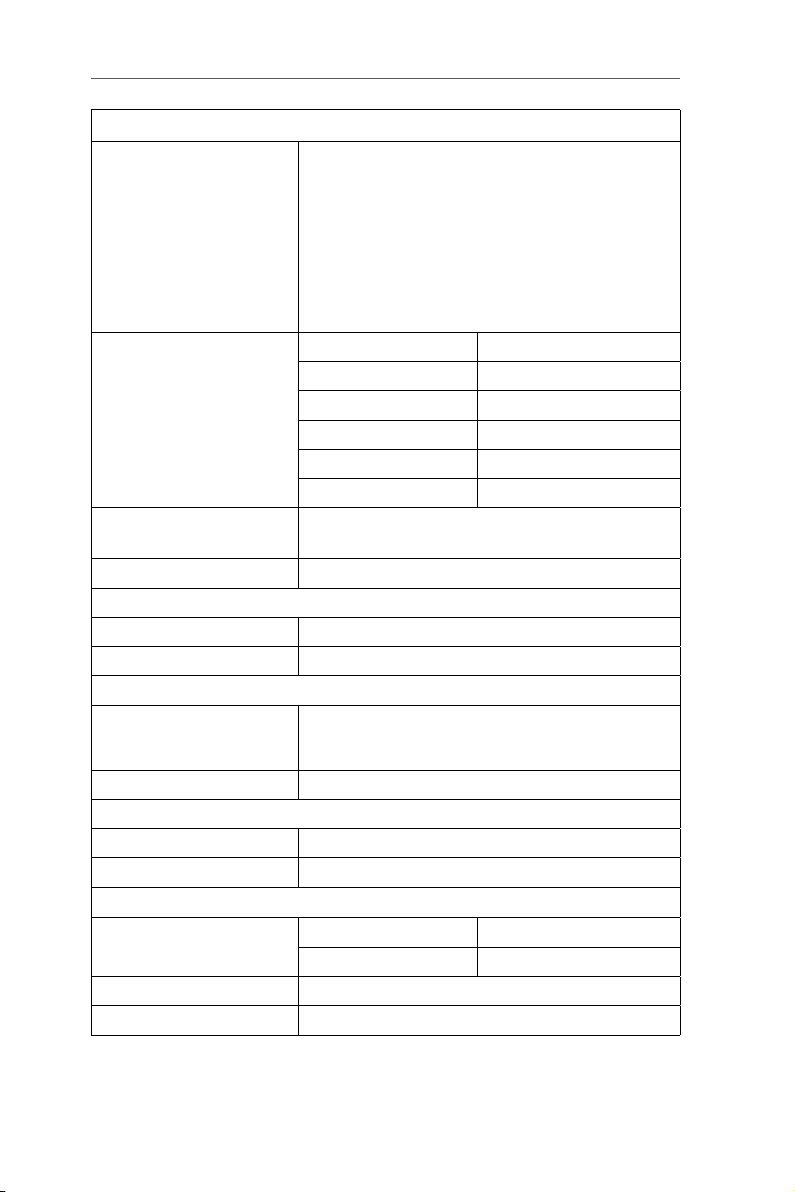
Assembled prototype.
Your kit has been carefully checked. Both boards have been tested
individually. This manual explains how to assemble and calibrate
your kit. Calibration will allow you to become familiar with the unit,
and to be able to repeat it if the need arises later.
(All photos Eurocircuits unless otherwise stated)
2 MHz LCR Meter Kit AU2019 Assembly Manual
●6
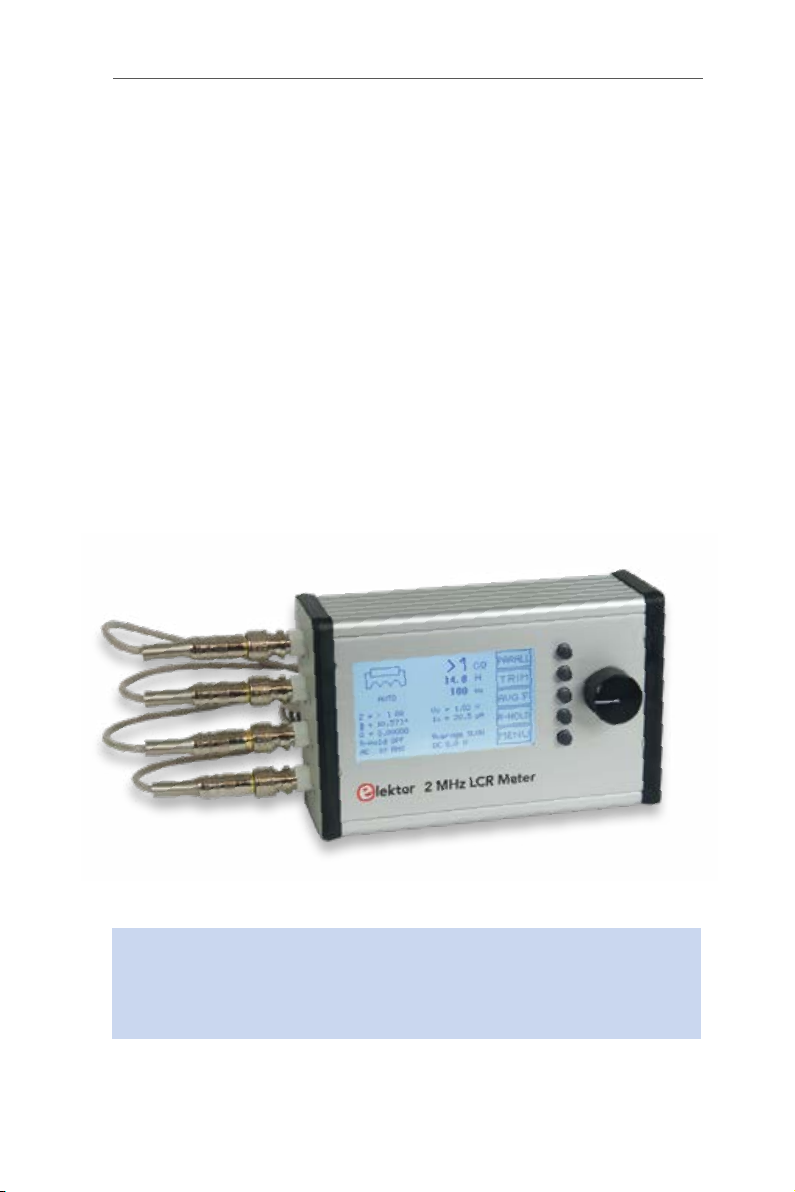
1 • Contents of your Kit
Check that the kit as received is complete. It must include:
3. Assembled MCU board (BNC connectors not mounted).
4. Assembled Display board (without the button of the rotary switch).
Note: the LCD has a protective film so transparent that it can go
unnoticed. It has no tab, but it can be easily peeled off by gently
lifting it at an angle with your fingernail.
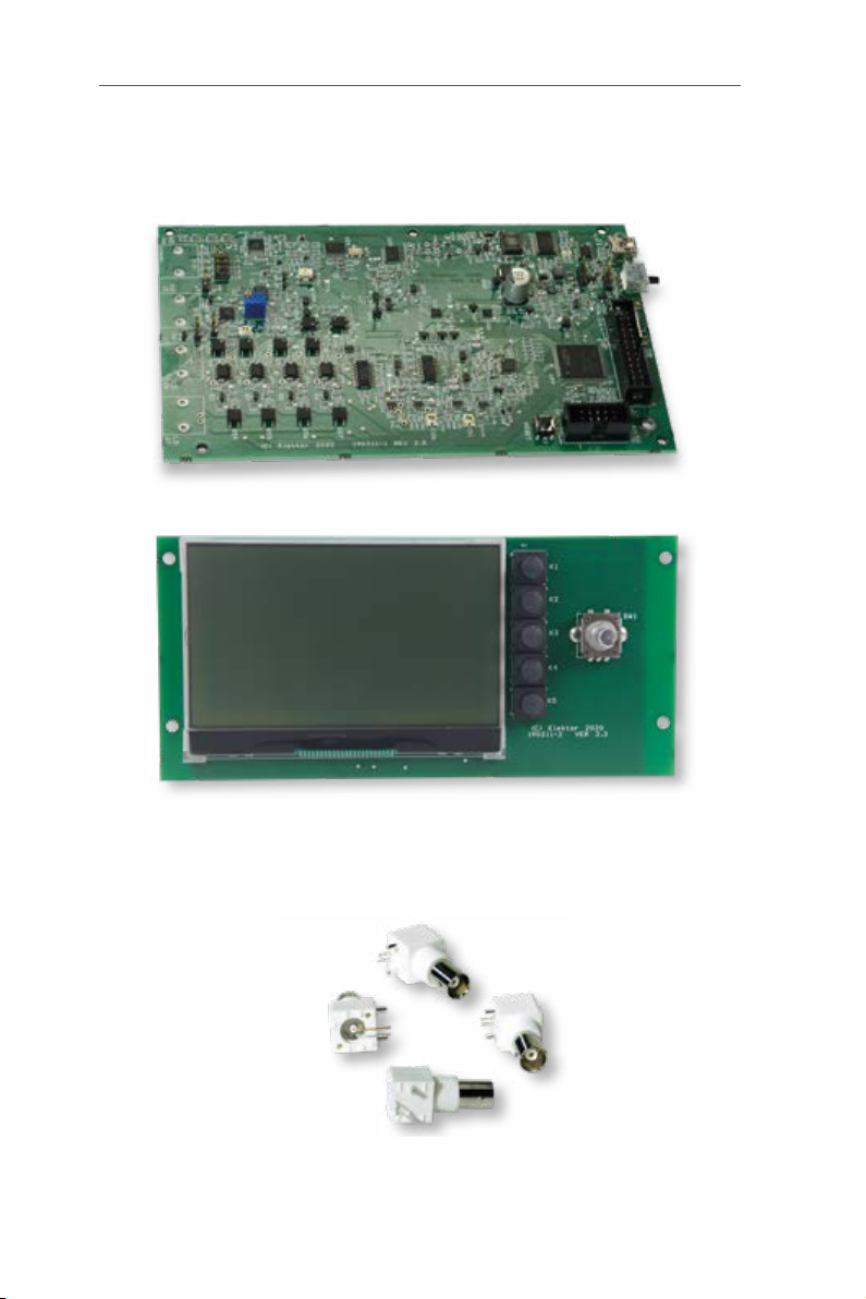
5. Four PCB-mount BNC connectors.
1 • Contents of your Kit
●7
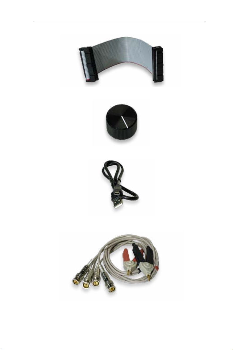
6. Flatcable (reversible).
7. Button, Ø 24mm.
8. USB cable (mini-USB / USB A).
9. Test clip with two Kelvin clips and 4 BNC connectors.
2 MHz LCR Meter Kit AU2019 Assembly Manual
●8
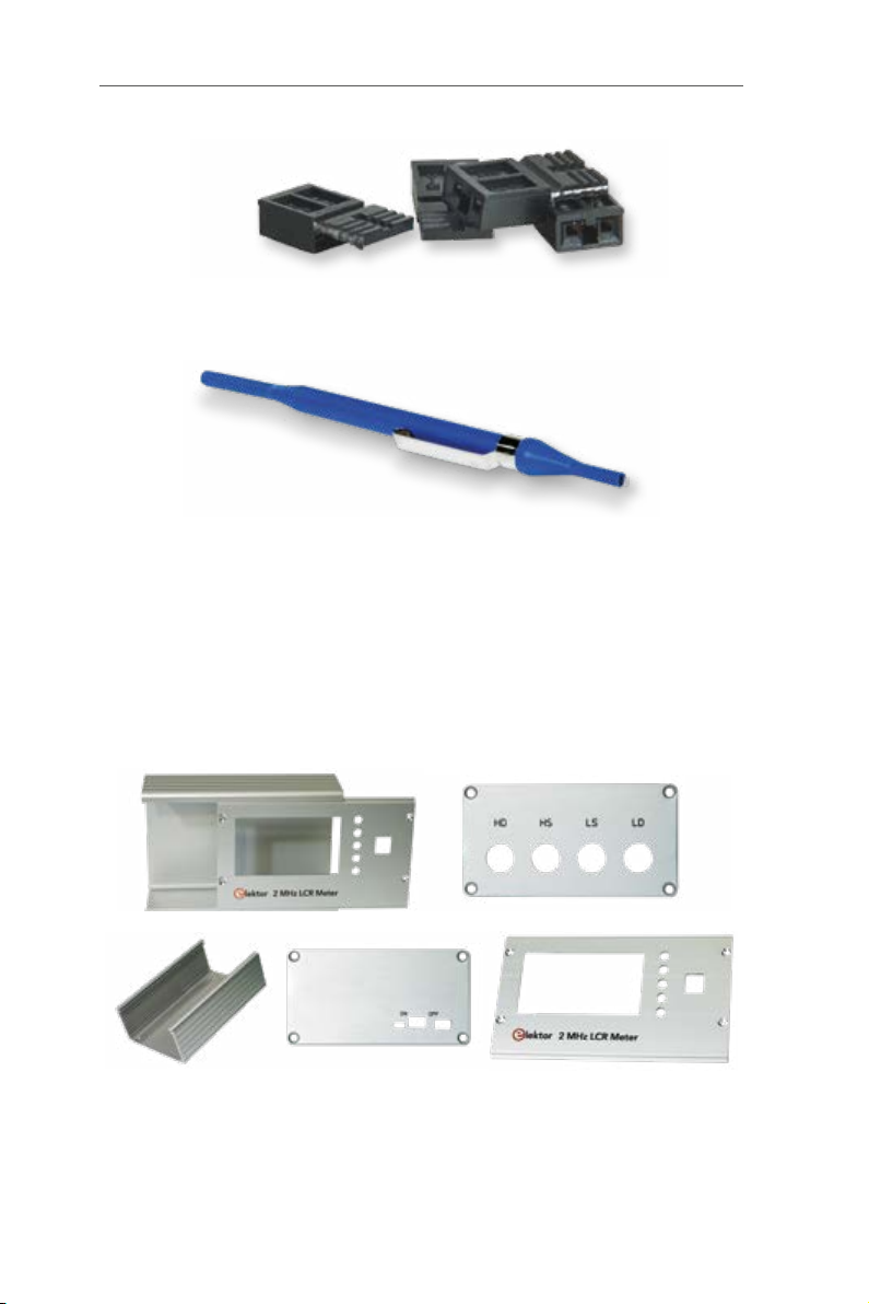
10. Four jumpers for settings during calibrations.
11. Screwdriver (trimming tool).
Hammond case.
- machined body
- machined and screen-printed front panel
- machined and screen-printed BNC side
- machined and screen-printed USB side
- 2 black plastic frames [+ special screws (8) and
rubber feet (4)]
12a. & b Machined and screen-printed Hammond case.
2 • Let’s mount the four BNC sockets
●9
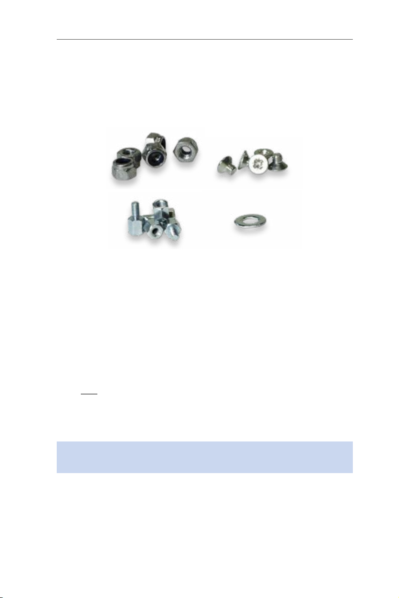
Screws and bolts.
- 5 x M3 male-female standoffs, 6 mm high
- 5 x 4 mm Pozidrive countersunk M3 screws
- 1 flat washer DM3, thickness 0.5 mm
- 5 x M3 self-locking nuts
13. Bolts & nuts etc.
And of course the User Manual you are reading right now!
Tools needed for assembly: Phillips screwdriver, spanner (not included).
2 • Let’s mount the four BNC sockets
Preferably solder the sockets one at a time. Position each one precise-
ly using the positioning pins, press it secure against the board, then
solder the two electrical contacts.
Only one of the two positioning pins should be soldered (unlike the
video on elektorTV!). This allows you to slightly modify the position of the
sockets later, if you intend to use an HP standard test accessory (de-
signed for 22 mm distance between the BNC sockets).
Important: Do not use nuts to secure the BNC sockets to the side
panel of the enclosure.
3 • Let’s preassemble the Hammond case
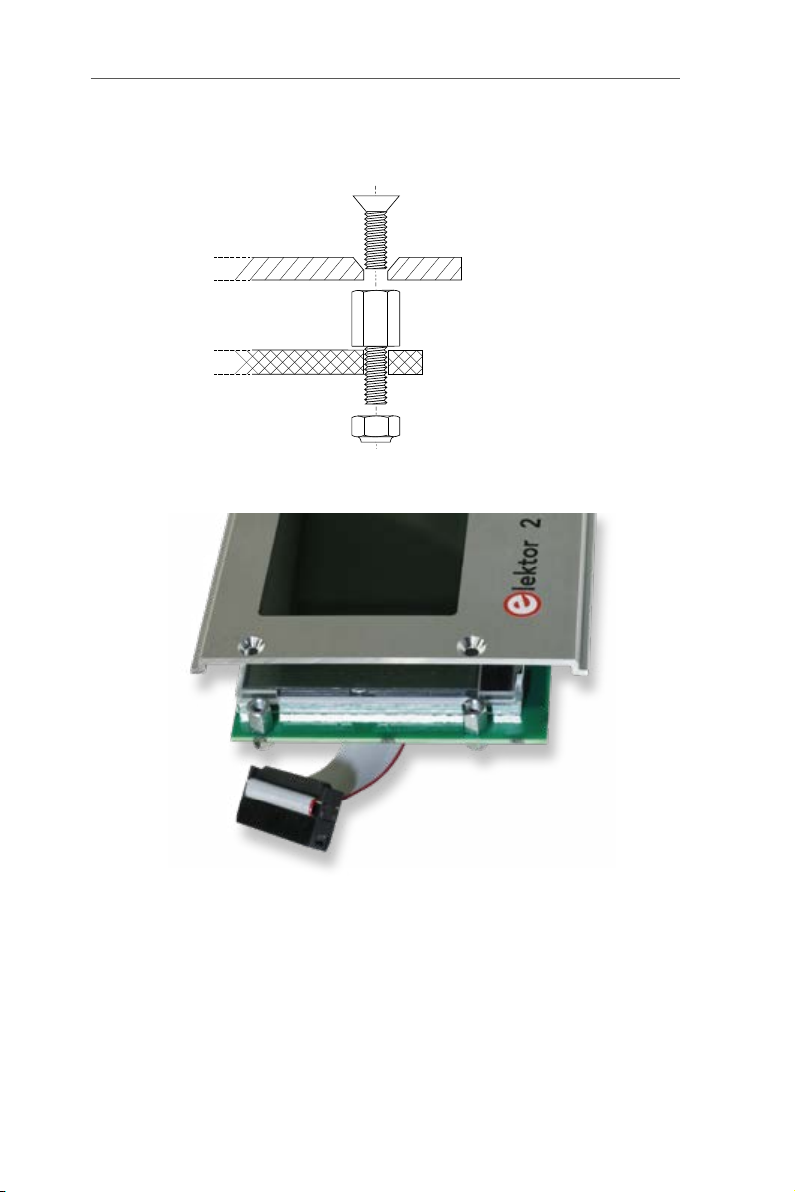
Mount four 6 mm M3 male-female standoffs into the four corners of the
Display PCB, without tightening the nuts.
2 MHz LCR Meter Kit AU2019 Assembly Manual
●10
Position the front panel on this board and secure it with 4 x 4 mm
countersunk screws, then tighten the nuts.
4 mm
M3 (Prevailing Torque
Type Hex Thin Nut)
Front Panel
6 mm standoff MF
Display PCB
14a. Mounting of the M3 male-female standoffs.
14b. Positioning the front panel on this Display board.
Mount the knob on the rotary encoder shaft and connect the flatcable
to J1 on the Display board. Slide the MCU board between the first two
guide rails counting from the bottom of the case, with the front panel
slid in its own guides. Then connect the second header of the flatcable
to J14 on the MCU board.
Note: The hole in the bottom of the case must be on the side of J14.
Ce manuel convient aux modèles suivants
1
Table des matières
Autres manuels Elektor Instrument de mesure

Manuels Instrument de mesure populaires d'autres marques


Endress+Hauser
Endress+Hauser Proline Promag 50 Caractéristiques techniques

Siemens
Siemens SITRANS F Coriolis FCT030 Manuel de la liste des pièces

KLINGER
KLINGER CMF V Series Manuel utilisateur

EXFO
EXFO FTB-2 Manuel d'exploitation et d'entretien

Keysight
Keysight M8290A Manuel utilisateur

ADTEK
ADTEK MW-5 Manuel utilisateur