Ekinex KNX FF Series Manuel utilisateur

1
Pushbutton FF series KNX
Codes:
EK-ED2-TP-... (with LED, temperature sensor and
temperature room controller)
EK-E32-TP-... (basic pushbutton)
white) (*) e.g. as a status feedback or orientation night-
light. Pressing a rocker, the device sends on the bus a
telegram, which is received and executed by one or more
KNX actuators depending on the conguration carried
out. The device is powered by the KNX bus line with a
SELV voltage 30 Vdc and does not require auxiliary po-
wer.
Main functional characteristics
• On/off switching of single loads or groups of loads
• Dimming of lighting devices
• Control of motor drives (for roller shutters, blinds, cur-
tains, etc.)
• Room temperature regulation (*)
• Logic functions
• Sending on the bus of values (temperature, bright-
ness, etc.)
• Switching to forced functioning (lock)
• Recalling and saving of scenes
• Measuring of room temperature through integrated
sensors (*)
• Different functions programmable for short pressure /
long pressure of a rocker
• Status feedback or orientation nightlight through 2-co-
lour programmable LEDs (*)
Other characteristics
• Housing in plastic material
• Wall installation in ush mounting box
• Protection degree IP20 (according to EN 60529)
• Classication climatic 3K5 and mechanical 3M2 (accor-
ding to EN 50491-2)
• Pollution degree 2 (according to IEC 60664-1)
• Weight 80 g (with mounting support)
• Dimensions 82 x 79 x 19 mm (WxHxD)
Technical data
• Power supply 30 Vdc from KNX bus line
• Current consumption < 15 mA
• Power from bus < 360 mW
Environmental conditions
• Operating temperature: - 5 ... + 45°C
• Storage temperature: - 25 ... + 55°C
• Transport temperature: - 25 ... + 70°C
• Relative humidity: 95% not condensing
KNX device for switching and control of single loads or
groups of loads and room temperature regulation. It has
to be used in KNX installations for control of homes and
buildings.
Description
The ekinex®pushbutton of FF series is a KNX S-mode
device for on/off switching of loads, dimming of lighting
devices, controlling of motor drives or other programma-
ble switching and control functions. The integrated tem-
perature sensor allows the use as a room or zone tem-
perature controller (*). It is equipped with an integrated
KNX bus communication module and is designed for wall
installation on ush-mounting box. Each channel can be
freely congured to carry out 1 or 2 bus functions and
is provided with programmable LED (blue/green or red/
Datasheet STEKED32TP_EN
TP1
S
Device code LED colours Mounting
EK-ED2-TP blue / green with frame of the
form or ank series
EK-ED2-TP-RW red / white
EK-ED2-TP-BG-NF blue / green without frame (‘NF series)
with black side prole
EK-ED2-TP-RW-NF red / white
EK-ED2-TP-BG-NFW blue / green without frame (‘NF series)
with white side prole
EK-ED2-TP-RW-NFW red / white
EK-E32-TP n.a. (*) with frame of the
form or ank series
EK-E32-TP-NF n.a. (*) without frame (‘NF series)
with black side prole
EK-E32-TP-NFW n.a. (*) without frame (‘NF series)
with white side prole
REFLEKED2TP
Completed with frame EK-FOQ-... (form)
and square rockers EK-TQQ-...
Completed with frame EK-FLQ-... (ank)
and rectangular rockers EK-TRO-...
Completed as ‘NF series (without frame)
with square rockers EK-TQQ-...
Completed as ‘NF series (without frame)
with rectangular rockers EK-TRO-...
Versions
*) The programmable LEDs, the temperature sensor
and the room temperature control function are available
for EK-ED2-TP-... versions only.

2
Delivery
The delivery of the pushbutton includes a metallic support
for round ush-mounting box, the xing screws (2 pairs)
and the KNX terminal block for connection of the bus line.
Accessories for the pushbutton
The pushbutton is completed through a separate order of:
• a set of rockers that allows the use it as 2-fold or
4-fold pushbutton;
• a square frame of the ekinex® form or ank series (not
for the ‘NF - No Frame versions).
Rockers
Three-positions rockers with central neutral position have
to be mounted on the pushbutton. Pushing one side of
a rocker (for example the upper one), the pushbutton
sends on the bus a telegram for switching on, increasing
the brightness of luminaires or raising the blinds, while
pushing the other side (for example the lower one), it sen-
ds a telegram for switching off, reducing the brightness of
luminaires or lowering the blinds. Each channel is equip-
ped with LEDs which can be freely programmed as status
feedbacks of the loads and as orientation nightlight (EK-
ED2-TP versions only.
Mounting
The device has degree of protection IP20, and is there-
fore suitable for use in dry interior rooms. Mounting the
device carry out the following steps:
• x the metallic support (5) with the pair of screws (6) on
the ush-mounting box (7) equipped with xing holes at
60 mm distance;
• insert pushbutton (3) in the metallic support (5).
Mounting the device follow also the indication TOP (ar-
row tip pointing up) on the front side of the device;
• snap a square frame (4) of the form or ank series, in-
serting it from the rear of the pushbutton (3);
• enter the bus terminal block, previously connected to
the bus cable in its slot on the rear side (see also: “Con-
nection of the KNX bus line”). At this point it is recom-
mended to carry out the commissioning of the device
(see also “Conguration and commissioning”) or at le-
ast the download of the physical address;
• fasten the device on the metallic support supplied with
the pair of screws (2);
• snap the rockers (1) for the operation of the device.
Code set of
rockers *
Appea-
rance
Nr. and type of
rockers
Rockers modu-
larity [mm]
EK-TRV-xxx 2 rectangular 40 x 80
EK-TQQ-xxx 4 square 40 x 40
EK-TRO-xxx 4 rectangular 80 x 20
(*) To be completed with the extension for colour and material
Note on installation of rockers
To assemble the rockers on their seats, the xing teeth
must be aligned vertically.
mounting
not possible
(xing teeth
in horizontal)
correct
mounting
Frame
The pushbutton can be completed by a square 1-fold fra-
me of the ank or form series. Using the templates EK-
DFO and EK-DFL it is also possible mounting side by side
two devices of FF series both completed by square fra-
mes respectively of form or ank series.
Code * Material Package Dimens.
[mm]
EK-FOQ-GAx plastic
1 pcs. 86 x 86
EK-FOQ-GBx metal
EK-FLQ-GAx plastic
1 pcs. 94 x 80
EK-FLQ-GBx metal
(*) To be completed with the extension for colour and material
ESEKED2TP
1 2 3 4 5 7
6
1) Rockers (to be ordered separately)
2) Fixing screws (for device)
3) Device
4) Frame of form or ank series (to be ordered separately)
5) Metallic mounting support
6) Fixing screws (for metallic support)
7) Flush-mounting box (not delivered by ekinex)
Note. The set of rockers and the optional frame for
completing the device have to be ordered separa-
tely. For more information, see also the ekinex®pro-
duct catalog or browse www.ekinex.com
iNote. The screws supplied in the package are su-
itable for standard installations. For more specic
applications, where the screws have to be replaced,
only at-head screws must be used. The screws for
the metal support must be tightened with a max. tor-
que of 1.0 Nm.
i
Note. The supplied plastic screws (# 2) must be
used exclusively to x the push-button panel in
position, therefore they must not be tightened with
excessive force (max. torque 0.4 Nm).
i
3
Use as a room temperature controller (EK-ED2-
TP versions only)
The pushbutton can be also used as a room temperature
controller for single-stage heating/cooling systems with
radiators, radiant panels and electrical heaters. As the de-
vice has no user interface, it must receive the operational
parameters by the bus (e.g. operating mode, seasonal
conduction mode or a change of the setpoint value).
Main functional characteristics (room temperature con-
troller)
• Temperature measuring through integrated sensor with
possibility of sending the value on the bus
• 2-point (on/off) or proportional (PWM or continuous)
room temperature regulation
• Seasonal conduction modes: heating and cooling with
possibility of changeover via bus or automatic depen-
ding on the conguration
• Operating modes: comfort, standby, economy and bu-
ilding protection with different setpoint for heating and
cooling
• Automatic switching of the operating modes triggered
by window opening/closing
• Weighted average of two temperature values
• Temperature control alarm
• Anti-locking function for valves (hydronic systems)
Switching, display and connection elements
The device is equipped with four mechanisms for
switching, four LEDs for each channel (EK-ED2-TP ver-
sione only), a programming LED and a programming pu-
shbutton (on some versions only) and a terminal block for
connection of the bus line.
Note. Programming pushbutton and LED are ac-
cessible from the front side of the device. It is better
addressing the device before the nal assembly of
rockers and frame. Once the addressing has been
performed, the device conguration can be later
downloaded without pressing the programming pu-
shbutton.
i
The pushbutton has to be mounted on a round or square
ush-mounting box with distance between xing holes of
60 mm. If necessary, the metallic support for mounting
on the wall box can also be ordered separately using the
code EK-SMQ-71.
1,50 m
min 0,3 m
Connection of the KNX bus line
The connection of the KNX bus line is made with the ter-
minal block (black/red) included in delivery and inserted
into the slot of the housing.
Characteristics of the KNX terminal block
• spring clamping of conductors
• 4 seats for conductors for each polarity
• terminal suitable for KNX bus cable with single-wire
conductors and diameter between 0.6 and 0.8 mm
• recommended wire stripping approx. 5 mm
• color codication: red = + (positive) bus conductor,
black = – (negative) bus conductor
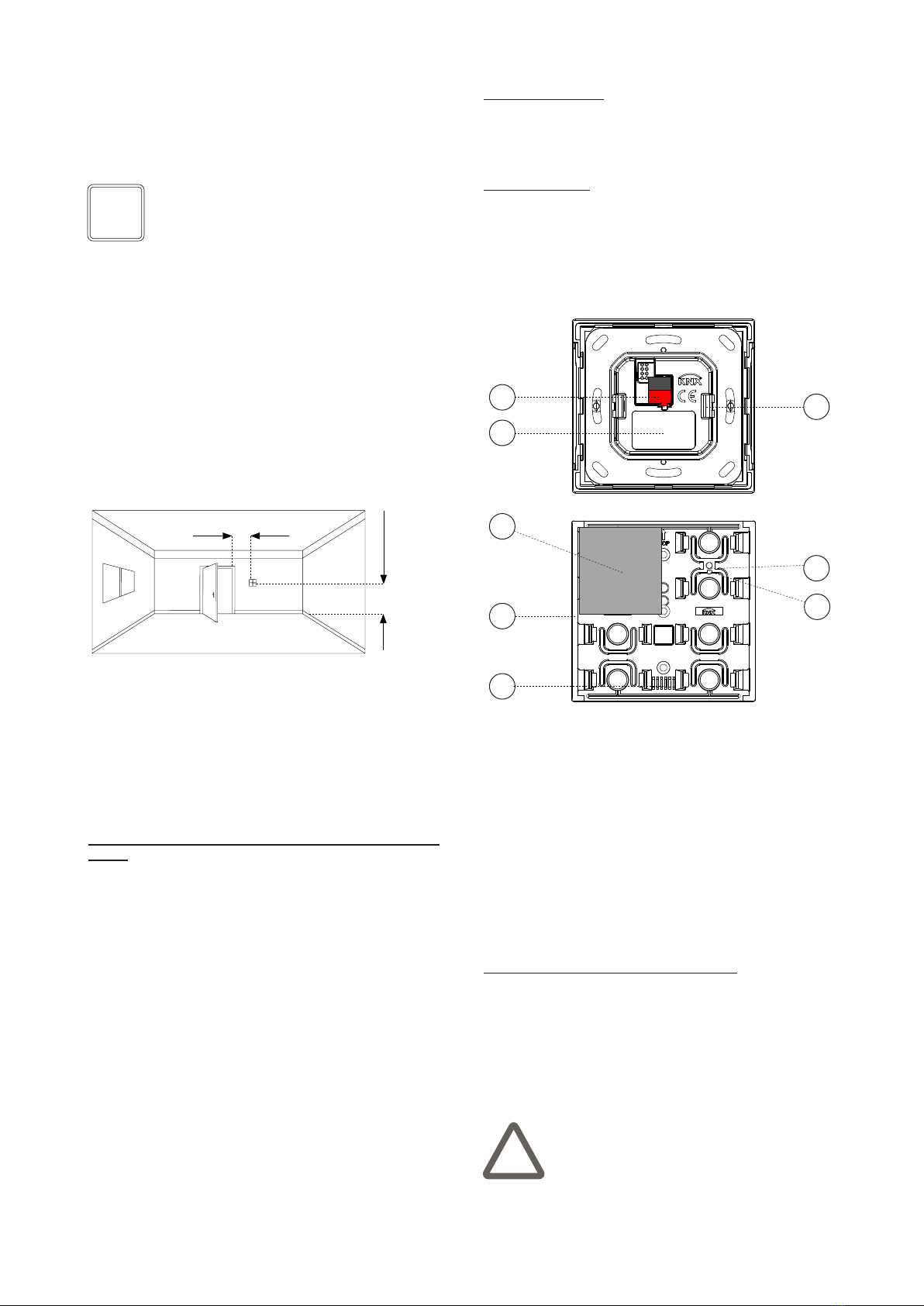
1) Connection terminal block for KNX bus line
2) Product label
3) Adapter
4) Rocker (in the example: 30 x 30 mm square type)
5) LED-lightguide
6) Positioning of the temperature sensor
7) Programming pushbutton (on some versions only)
8) Programming LED (on some versions only)
DCEKED2TP
2
3
1
6
7
8
4
5
Switching elements
• Pushbutton (7) for switching between the normal and
programming operating modes (on some versions only)
• One, two or four rockers (4) for independent switching
of single or group of loads
Display elements
• Red LED (8, on some versions only) for indication of
the active operating mode (on = programming, off =
normal operation)
• Freely programmable LED with lightguide (5) e.g. for
feedback status and orientation nightlight LED (for EK-
ED2-TP versions only).
Warning! The electrical connection of the device
can be carried out only by qualied personnel. The
incorrect installation may result in electric shock or
re. Before making the electrical connections, make
sure the power supply has been turned off.
!
Mounting position
If the integrated sensor is used for temperature regulation
(EK-ED2-TP versions only), the device has to be installed
preferably lon an internal wall at the height of 1,5 m and
at least 0,3 m far from doors. The device can not be instal-
led close to heat sources such as radiators or houshold
appliances or in position subjected to direct sunlight. If
necessary, for the regulation can be used a weighted ave-
rage value between the value measured by the integrated
sensor and a value received via bus by another KNX de-
vice.

4
Product
code
Application program
(## = release)
Communica-
tion objects
(nr. max)
Group
adresses
(nr. max)
EK-ED2-TP
APEKED2TP##.knxprod
229 254
EK-E32-TP
APEKED2TP##.knxpro
229 254
Conguration
For the conguration of the device parameters the corre-
sponding application program or the whole ekinex®pro-
duct database must be loaded in the ETS program. For
detailed information on conguration options, refer to the
application manual of the device available on the website
www.ekinex.com.
Commissioning
For commissioning the device the following activities are
required:
• make the electrical connections as described above;
• turn on the bus power supply;
• switch the device operation to the programming mode
as described in the next table;
• download into the device the physical address and the
conguration with the ETS®program.
At the end of the download the operation of the device
automatically returns to normal mode; in this mode the
programming LED (where available) and/or the LEDs of
the second color (for EK-ED2-TP-...) are turned off. Now
the bus device is programmed and ready for use.
Reset of the device
To reset the device:
• if the programming button is present, remove the con-
nection to the bus network by extracting the bus ter-
minal from its seat. Keeping the programming button
pressed, reinsert the bus terminal in its seat; the pro-
gramming LED ashes quickly. Release the program-
ming button and extract the clamp again; the reset has
been performed.
• If, on the other hand, the programming button is not
present, repeat the programming sequence by holding
down the buttons for about 10 seconds. The LEDs of
the second color rst ash, then go off; the reset has
been performed.
Warning! In order to supply the KNX bus lines use
only KNX bus power supplies (e.g. ekinex EK-AB1-
TP or EK-AG1-TP). The use of other power supplies
can compromise the communication and damage
the devices connected to the bus.
!
Note. The conguration and commissioning of KNX
devices require specialized skills. To acquire these
skills, you should attend the workshops at KNX cer-
tied training centers.
i
Conguration and commissioning
Conguration and commissioning of the device require
the use of the ETS®(Engineering Tool Software) program
V4 or later releases. These activities must be carried out
according to the design of the building automation system
done by a qualied planner.
Warning! The reset restores the device back to the
state of delivery from the factory. The address and
the value of the parameters set during conguration
will be lost.
!
+-
Bus
KNX
ELEKED2TP
Product
code
FW
version
Programming
sequence
Visual
feedback
EK-ED2-
TP
04.xxx
and pre-
vious
Pressing the pro-
gramming button
Program-
ming LED
on steady.
from
05.xxx
to
06.018
Simultaneous press
of the rst and last
button on the left
side for 5 seconds. All LEDs of
the second
color ash.
Program-
ming LED (if
present) on
steady.
06.019
and
later
Simultaneous pres-
sing of the rst but-
ton on the left side
and the last button
on the right side for
5 seconds. All LEDs of
the second
color ash.
EK-E32-TP All Pressing the pro-
gramming button
Program-
ming LED
on steady.

5
Warnings
• Installation, electrical connection, conguration and
commissioning of the device can only be carried out by
qualied personnel in compliance with the applicable
technical standards and laws of the respective countri-
es
• Opening the housing of the device causes the imme-
diate end of the warranty period
• In case of tampering, the compliance with the essential
requirements of the applicable directives, for which the
device has been certied, is no longer guaranteed
• ekinex®KNX defective devices must be returned to the
manufacturer at the following address: EKINEX S.p.A.
Via Novara 37, I-28010 Vaprio d’Agogna (NO) Italy
Other information
• This datasheet is aimed at installers, system integra-
tors and planners
• For further information on the product, please contact
the ekinex®technical support at the e-mail address:
com
• Each ekinex®device has a unique serial number on
the label. The serial number can be used by installers
or system integrators for documentation purposes and
has to be added in each communication addressed to
the EKINEX technical support in case of malfunctioning
of the device
• KNX®and ETS®are registered trademarks of KNX As-
sociation cvba, Brussels
© EKINEX S.p.A. The company reserves the right to make changes to this
documentation without notice.
Dimensions [mm]
Marks
• KNX
• CE: the device complies with the RoHS III Directive
(2011/65/EU) and the Electromagnetic Compatibility
Directive (2014/30/EU). Tests carried out according to
EN 63044-5-1:2019; EN 63044-5-2:2019
Disposal
At the end of its useful life the product
described in this datasheet is classied
as waste from electronic equipment in
accordance with the European Direc-
tive 2012/19/EU (WEEE recast), and
cannot be disposed together with the
municipal undifferentiated solid waste.
Warning! Incorrect disposal of this product may
cause serious damage to the environment and hu-
man health. Please be informed about the correct
disposal procedures for waste collecting and pro-
cessing provided by local authorities.
!
Documentation
This datasheet refers to the release 6.0 of the ekinex®
device EK-ED2-TP-... and to the release 1.0 of the ekinex
device EK-E32-TP-..., and is available for download at
www.ekinex.com as a PDF (Portable Data Format) le.
File name Device release Updating
STEKED2E32TP_EN_v.4.2.pdf 6.0 05 / 2023
1.0
94
80
8
86 8
86
Square frame form
series EK-FOQ-...
Square frame ank
series EK-FLQ-...
3
39,5
80
3
39,5
39,5
80
19
3
Set rockers
EK-TRV-...
Set rockers
EK-TQQ-...
Set rockers
EK-TRO-...
Maintenance
The device is maintenance-free. To clean use a dry cloth.
It must be avoided the use of solvents or other aggressive
substances.
Ce manuel convient aux modèles suivants
9
Table des matières
Autres manuels Ekinex Contrôleurs

Ekinex
Ekinex EK-HA1-TP Manuel utilisateur

Ekinex
Ekinex EK-ET2-TP Manuel utilisateur

Ekinex
Ekinex EK-HH1-TP Manuel utilisateur

Ekinex
Ekinex KNX EK-FB1-TP Manuel utilisateur

Ekinex
Ekinex EK-FE1-TP Manuel utilisateur

Ekinex
Ekinex 71 Series Manuel utilisateur

Ekinex
Ekinex EK-HH1-TP Instructions d'utilisation

Ekinex
Ekinex EK-GC1-TP Manuel utilisateur

Ekinex
Ekinex EK-HE1-TP Manuel utilisateur

Ekinex
Ekinex EK-ES2-TP Instructions d'utilisation


