Ekinex EK-HA1-TP Manuel utilisateur

Page 1
Actuators / controllers for fan_coil
Code : EK-HA1-TP / EK-HB1-TP / EK-HC1-TP
Data sheet STEKHC1TP_EN
KNX devices with function of actuator and tempera-
ture controller for convectors and fan-coil. To be used
in KNX installations for control of homes and build-
ings.
Descrizione
The EK-Hx1-TP series includes three devices ekinex®
KNX S-mode suitable for temperature control
applications. The EK-HC1-TP is used for installations in
2 or 4-pipe hydraulic distribution systems with ON /OFF
control of an electrothermal actuator on a shut-off valve;
control of a 3-speed fan or 0-10 V control of a fan with
brushless motor; this version allows manual control of
the outputs through the membrane pushbuttons. The
EK-HA1-TP version is used for installations in 2-pipe
hydraulic distribution systems with ON /OFF control of
an electrothermal actuator on a shut-off valve and a 3-
speed fan. EK-HB1-TP version is used for installations
in 2-pipe hydraulic distribution systems with ON /OFF
control of an electrothermal actuator on a shut-off valve
and 0-10 V control of a fan with brushless motor.
The devices can be configured as actuators for the
control of a fan and a maximum of two shut-off valves
ON /OFF on the heat exchange coils , in combination
with a room thermostat installed on the KNX network .
The devices can be configured as controllers / actuators
with acquisition of the temperature of a room sensor
KNX or via a sensor installed on the return duct and
connected to one of the analog inputs.
Functions
EK-HA1-TP
•Power supply from the bus and auxiliary power
supply
•230 Vac 50/60 Hz
Control of 2-pipe hydraulic distribution systems with
•shutoff valve ON/OFF (1 SPST relay)
3 relay outputs to control a 3-speed fan
2 inputs freely configurable for acquisition of passive
•temperature sensors (10 kΩ NTC at 25°C) or as
•potential-free binary inputs
EK-HB1-TP
•Power supply from the bus and auxiliary power
supply 230 Vac 50/60 Hz
•Control of 2-pipe hydraulic distribution systems with
shutoff valve ON/OFF (1 SPST relay)
•1 output 0-10 V for control of a fan with brushless
motor
•2 inputs freely configurable for acquisition of passive
temperature sensors (10 kΩ NTC at 25°C) or as
potential-free binary inputs
EK-HC1-TP
•Power supply from the bus and auxiliary power
supply 230 Vac 50/60 Hz
•Control of 2 or 4-pipe hydraulic distribution systems
•With shutoff valve ON/OFF (2 SPST relays)
•Control of a 3-speed fan or 0-10 V control of a fan
with brushless motor
•3 inputs freely configurable for acquisition of passive
temperature sensors (10 kΩ NTC at 25°C) or as
potential-free binary inputs
Integrated Temperature Controller
•Settings via bus with Setpoint Setpoint single or
related activated through the way HVAC System
•ON / OFF or PWM ( pulse width modulation ) of the
water flow to the heat exchange coils
•ON / OFF at 1-3 windows with hysteresis or PI
( Proportional Integral ) of the air flow of the fan
•Switching heating / cooling from the bus or
automatically according to the ambient temperature
or according to the temperature of the fluid at
discharge
•Ability to enable a compensation curve climatic
cooling
•Automatic hot-start and cold -start the fan based on
the actual temperature of the heat exchanger
•Trigger fan in case of stratification in large
environments
•Function monitoring condensate level
•Monitoring function operating hours with signaling
replacement filter
Technical Data
•Bus voltage KNX :29 Vdc
•Operating voltage : 230 Vac 50/60 Hz
•3 Out for Fan relay (interlocked) with monostable
relays (5A/230Vac), contacts with voltage and
external power supply terminal (EK-HA1-TP and
EK-HC1-TP version)
•1 Out 0…10V for high impedance inputs (EK-HB1-
TP and EK-HC1-TP version)
•1 Out with monostable relay (5A/230Vac) SPST type
single pole single throw, to control the valve of
the ,thermal battery. Contact without voltage.(EK-
HA1-TP ed EK-HB1-TP version)
REAEKHC1TP

Page 2
•1 Out with monostable relay (5A/230Vac) SPST type
single pole single throw, to control the valve of
the ,thermal battery. Contact without voltage(EK-
HC1-TP version)
•Current consumtion KNX bus:< 10 mA
•Plastic container
•Installatio type : board on EN 60715 DIN rail
•Protection rating: IP 20 in according with EN 60529
•Climate and mechanics classification : 3K5 and 3M2
in according EN50491-2
•Protection class III in according with EN 60664-1
•Pollution 2 in according with IEC 60664-1
•Dimension : 72 x 90 x 60 mm (LxHxP)
Enviromental Conditions
•Operating temperature: - 5 ... + 45°C
•Storage Temperature: - 25 ... + 55°C
•Transport Temperature: - 25 ... + 70°C
•Relative Humidity : 95%
Switching, display and connection elements
All devices are equipped with a button , a LED pro-
gramming, KNX terminals for connecting the outputs,
additional line voltage and KNX bus line.
The EK-HC1-TP version is equipped with membrane
buttons and LEDs.
1 ) Input and output terminals
2 ) membrane buttons for manual activation of the outputs
3 ) LED status indicators manual output
4 ) LED indicator was manually entered
5 ) Button insertion manually
6 ) Programming button
7 ) LED indication of programming mode
8 ) Terminal KNX bus line
9 ) Terminal for auxiliary power supply 230 Vac
10 ) LED indication of alarm
Command Elements
•Pushbutton (6) for switching between the normal
operation mode and programming
•Membrane pushbutton (5) for switching between the
operating modes forced ( buttons on the front
active ) or automatic ( buttons on the front non-
active )
•Membrane pushbuttons (2) for forcing the fan speed
Thanks to the lever switches located on the front of the
device, the connected loads can be manually controlled
in the absence of voltage on the KNX bus or when the
programming has not yet been carried out.
Note. For the version with membrane keyboard
EK- HC1 - TP , the manual control of the terminal is possi-
ble if the voltage is present both on the KNX bus that the
mains voltage
.
Display elements
•Red LED (7)for displaying the active operating
mode of the device (on = programming, off = normal
operation)
•Red LED (4) for indicating the operating mode ( on
= forced operation , off = automatic)
•Green LEDs for status indication of the speed set
manually for the fan and for the manual setting of
the output valves
•Red LED (10) to give the status of alarm
Mounting
The device has degree of protection IP20, and is
therefore suitable for use in dry interior rooms.
The housing is made for rail mounting according to
EN 60715 in boards or cabinets for electrical
distribution.
The installation is in horizontal position, the correct
position is when the KNX bus terminal is located at the
bottom and the terminals for the outputs are located at
the top.
For the installation of the device on the rail proceed as
follows:
•with the aid of a tool bring the locking device in the
fully lowered position (1);
•place the upper edge of the rear inner profile on the
upper edge of the rail (2);
•rotate the device towards the rail (3);
•push the locking device upward until it stops (4).
1
2
3
4
Before removing the device, be sure the inputs have
been disconnected and the bus terminal has been
extracted from its slot. Use a screwdriver to slide down
the locking device and remove the device from the rail.
Note. For the EK-HC1-TP version it is recommended that
the installation of the device always ensure the full
accessibility of the front side to allow the operation of the
pushbuttons
1
2
3
4
5
6
7
8
9
10
DCEKHX1TP
Inserire codice immagine

Page 3
Connection of the KNX bus line
The connection of the KNX bus line is made with the
terminal block (black/red) included in delivery and
inserted into the slot of the housing.
Characteristics of the KNX terminal block
•spring clamping of conductors
•4 seats for conductors for each polarity
•terminal suitable for KNX bus cable with single-wire
conductors and diameter between 0.6 and 0.8 mm •
recommended wire stripping approx. 5 mm
•color codification:
red = + (positive) bus conductor
black = - (negative) bus conductor
Warning! In order to supply the KNX bus lines use only a
KNX bus power supply (e.g. ekinex EK-AB1- TP or EK-
AG1-TP). The use of other power supplies can
compromise the communication and damage the devices
connected to the bus.
Connection of the 230 Vac line (all version)
The connection of the line is made with screw terminals
located on the upper front of the device.(Figure A).
Characteristics of the terminals
•screw clamping of conductors
•maximum cross section of conductor 2.5 mm²
(single wire)
•recommended wire stripping approx. 6 mm
•torque max 0.8 Nm
Warning! The electrical connection of the device can be
carried out only by qualified personnel. The incorrect
installation may result in electric shock or fire. Before
making the electrical connections, make sure the power
supply has been turned off..
a
Connection of KNX bus and 230 Vac power supply
Inputs/ Outputs Terminal
Terminals
Name
Signal Type
3-4
IN1
Input 1 configurable as passive probe
temperature ( sensor NTC 10k @
25 °C ) or as a binary input (potential
free)
5-6
IN2
2 freely configurable input
7-8
IN3
3 freely configurable input ( only EK -
HC1 - TP )
9-10
0-10V
Output 0 ... 10V ( for high impedance
inputs ) to control the fan with brushless
motor ( for EK- HB1 - TP and EK -HC1 -
TP )
11
C
common Input to control 3-speed motor
( for EK - HA1 - TP and EK - HC1 - TP )
12
V1
Relay output fed to control the fan
speed 1
( for EK - HA1 - TP and EK - HC1 - TP )
13
V2
Relay output fed to control the fan
speed 2
( for EK - HA1 - TP and EK - HC1 - TP )
14
V3
Relay output fed to control the fan
speed 3
( for EK - HA1 - TP and EK - HC1 - TP )
15-16
DO1
Potential free relay output to control ac-
tuator valve heat exchange
17-18
DO2
Potential free relay output to control ac-
tuator valve heat
( only EK - HC1 - TP )
The outputs that are not used for the command of the
terminal temperature control can be configured in ETS
for the control of actuators of lighting or drive .
Example
EK-HA1-TP:
3-speed fan, 2-pipe system, application with use of the internal
regulator and room sensor or on the recovery. attention to the
electrical connections. The outputs V1, V2, V3 and C1 must be
powered externally ( terminals 11 and 15) with the power phase:
because the system functions you must connect the other end of the
motor fan and the other end of the actuator to the conductor neutral.
IN1 43
C1211 V1 V2 1413 V3 1615 DO1 1817 DO2
IN2 65 IN3 87 0-10V 109-
+
230Vac
N
L
1 2 3
T
IN1 43
C1211 V1 V2 1413 V3 1615 DO1 1817
IN2 65 87 109
1 2
L N
Dev.
Line
Area
bus KNX
230Vac-50/60Hz
EK-HA1-TP
Fan-coil actuator/controller
+
-
Bus
KNX
L
N
230 Vac
50/60 Hz
EL1EKHx1TP

Page 4
EK-HB1-TP:
Fan 0...10V , 2-pipe system,application for residential; the product
can be used as a simple actuator in combination with the thermostat
ekinex EK - EP2 - TP or EK - EQ2 - TP. The actuator on the battery
can be of the 24 Vac ( diagram below).
EK-HB1-TP:
Fan 0...10V, 2-pipe system,
application for residential;
actuator valve for exchange battery powered at 24 Vac .
EK-HC1-TP:
Fan 3-speed, 4-pipe system , complete application. The fan can also
be a brushless motor with 0...10V. Actuators for shut-off valves of the
batteries warm and cold water supplied at 230 Vac.
EK-HC1-TP:
3-speed fan, 2-pipe system, complete application. In this case the
output DO2 (with relay 230 Vac and ability 16A) can be used to
control an additional stage of heating with electric battery.
EK-HC1-TP:
Fan 3-speed, 4-pipe system , complete application. The fan can also
be a brushless motor with 0...10V. Actuators for shut-off valves
supplied at 24 Vac of the batteries warm and cold water.
-+
230Vac
N
L
T
IN1 43
1211 14
13 1615 DO1 18
17
IN2 65 87 0-10V 109
1 2
L N
Dev.
Line
Area
bus KNX
-
+
230Vac-50/60Hz
EK-HB1-TP
Fan-coil actuator/controller
M
-+
230Vac
N
L
T
IN1 43
1211 1413 1615 DO1 1817
IN2 65 87 0-10V 109
1 2
L N
Dev.
Line
Area
bus KNX
-
+
230Vac-50/60Hz
EK-HB1-TP
Fan-coil actuator/controller
M
24Vac
230Vac
N
L
1 2 3
T
IN1 43
C1211 V1 V2 1413 V3 1615 DO1 1817 DO2
IN2 65 IN3 87 0-10V 109
1 2
L N
Dev.
Line
Area
bus KNX
-
+
230Vac-50/60Hz
31 DO1
2
DO2
EK-HC1-TP
Fan-coil actuator/controller
230Vac
N
L
1 2 3
T
IN1 43
C1211 V1 V2 1413 V3 1615 DO1 1817 DO2
IN2 65 IN3 87 0-10V 109
1 2
L N
Dev.
Line
Area
bus KNX
-
+
230Vac-50/60Hz
31 DO1
2
DO2
EK-HC1-TP
Fan-coil actuator/controller
230Vac
N
L
1 2 3
T
IN1 43
C1211 V1 V2 1413 V3 1615 DO1 1817 DO2
IN2 65 IN3 87 0-10V 109
1 2
L N
Dev.
Line
Area
bus KNX
-
+
230Vac-50/60Hz
31 DO1
2
DO2
EK-HC1-TP
Fan-coil actuator/controller
24Vac

Page 5
Configuration and commissioning
Configuration and commissioning of the device require
the use of the ETS® (Engineering Tool Software)
program V4 or later releases. These activities must be
carried out according to the design of the building
automation system done by a qualified planner.
Configuration For the configuration of the device
parameters the corresponding application program or
the whole ekinex® product database must be loaded in
the ETS program.
For detailed information on configuration options, refer
to the application manual of the device available on the
website www.ekinex.com
Product code
Application software
(## = version)
Communi-
cation
objects
(max nr.)
Group
adresses
(max nr.)
EK-HA1-TP
APEKHA1TP##.knxprod
45
254
EK-HB1-TP
APEKHB1TP##.knxprod
45
254
EK-HC1-TP
APEKHC1TP##.knxprod
63
254
Note. The configuration and commissioning of KNX
devices require specialized skills. To acquire these
skills, you should attend the workshops at KNX
certified training centers.
Commissioning
For commissioning the device the following activities
are required:
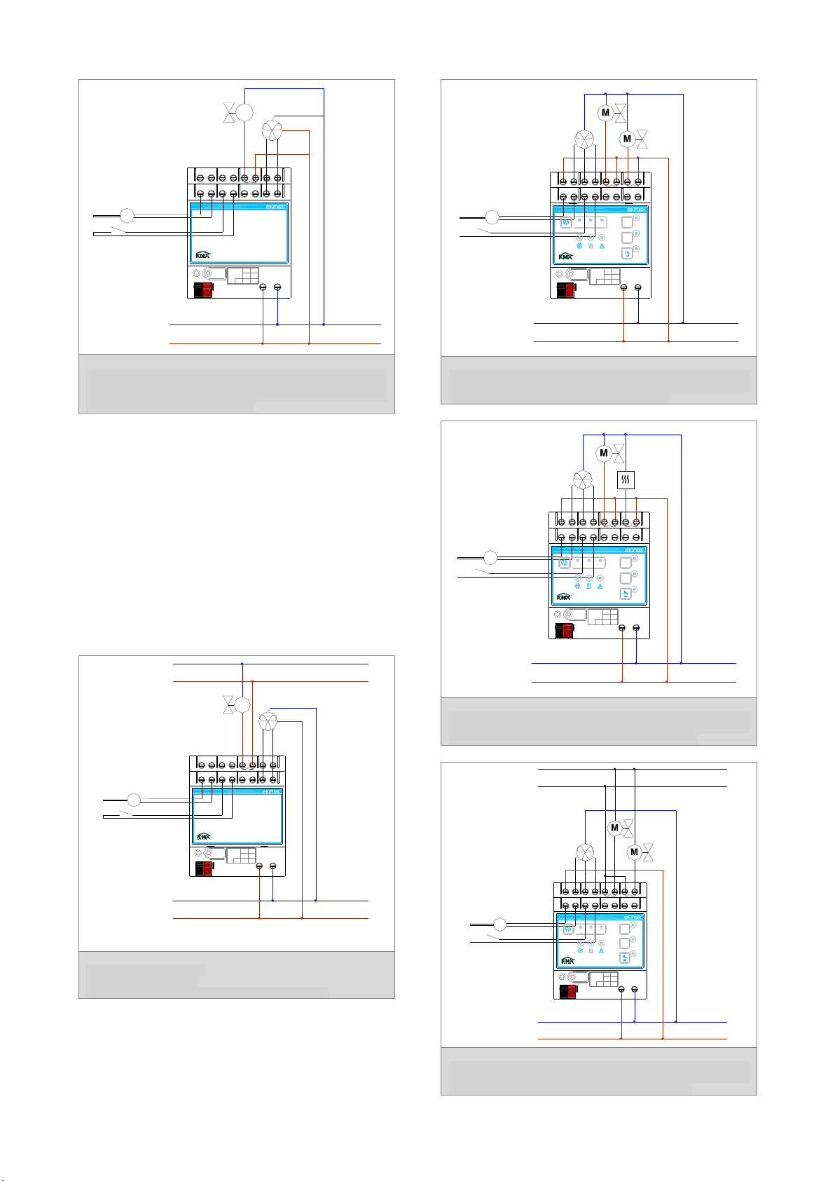
•make the electrical connections as described above;
•turn on the bus power supply;
•switch the device operation to the programming
mode by pressing the programming pushbutton
located on the front side of the housing. In this
mode of operation, the programming LED is turned
on;
•download into the device the physical address and
the configuration with the ETS® program.
At the end of the download the operation of the device
automatically returns to normal mode; in this mode the
programming LED is turned off. Now the bus device is
programmed and ready for use.
Dimensions [mm] (All versions)
Marks
the device complies with the Low Voltage
Directive (2006/95/EC) and the
Electromagnetic Compatibility Directive
(2004/108/EC).
Tests carried out according to
EN 50491-2:2010, EN 50491-3:2009,
EN 50491-4 - 1:2012, EN 50491-5-1:2010,
EN 50491-5-2:2010, EN 50428:2005
+A1:2007 + A2:2009
Maintenance
The device is maintenance-free. To clean use a dry
cloth. It must be avoided the use of solvents or other
aggressive substances.
Disposal
At the end of its useful life the product described in this
datasheet is classified as waste from electronic
equipment in accordance with the European Directive
2002/96/EC (WEEE), and cannot be disposed together
with the municipal undifferentiated solid waste.
Warning! Incorrect disposal of this product may cause
serious damage to the environment and human health.
Please be informed about the correct disposal
procedures for waste collecting and processing
provided by local authorities.
Documentation
This datasheet refers to the release A1.0 of the ekinex®
devices EK-HA1-TP, EK-HB1-TP and EK-HC1-TP, and
is available for download at www.ekinex.com as a PDF
(Portable Data Format) file.
Filename
Device release
Updating
STEKHx1TP_EN.pdf
A1.0
01/2016
Warnings
•Installation, electrical connection, configuration and
commissioning of the device can only be carried out
by qualified personnel in compliance with the
applicable technical standards and laws of the
respective countries
•The use of the device in security applications is not
allowed. The device may however be used for
auxiliary signaling functions
•Opening the housing of the device causes the
immediate end of the warranty period
•In case of tampering, the compliance with the
essential requirements of the applicable directives,
for which the device has been certified, is no longer
guaranteed
•ekinex® KNX defective devices must be returned to
the manufacturer at the following address: EKINEX
S.p.A. Via Novara 37, I-28010 Vaprio d’Agogna
(NO) Italy Other information
•This datasheet is aimed at installers, system
integrators and planners
•For further information on the product, please
contact the ekinex® technical support at the e-mail
address: [email protected] or visit the website
www.ekinex. Com
•KNX® and ETS® are registered trademarks of KNX
Association cvba, Brussels
© EKINEX S.p.A. The company reserves the right to make changes to
this documentation without notice.
90
72
DQEKHC1TP
Ce manuel convient aux modèles suivants
2
Table des matières
Autres manuels Ekinex Contrôleurs

Ekinex
Ekinex EK-AG1-TP Manuel utilisateur

Ekinex
Ekinex EK-FE1-TP Manuel utilisateur

Ekinex
Ekinex KNX FF Series Manuel utilisateur

Ekinex
Ekinex EK-ES2-TP Instructions d'utilisation

Ekinex
Ekinex KNX EK-FB1-TP Manuel utilisateur

Ekinex
Ekinex EK-GC1-TP Manuel utilisateur

Ekinex
Ekinex EK-HE1-TP Manuel utilisateur

Ekinex
Ekinex EK-HH1-TP Instructions d'utilisation

Ekinex
Ekinex EK-FF1-TP Manuel utilisateur

Ekinex
Ekinex EK-HH1-TP Manuel utilisateur


