7
USER MANUAL MULTISCAN MICROCHIP READER
T +49 7461 96 580 0 | F +49 7461 96 580 90 | export@eickemeyer.com | www.eickemeyer.com
3. NORMAL OPERATION
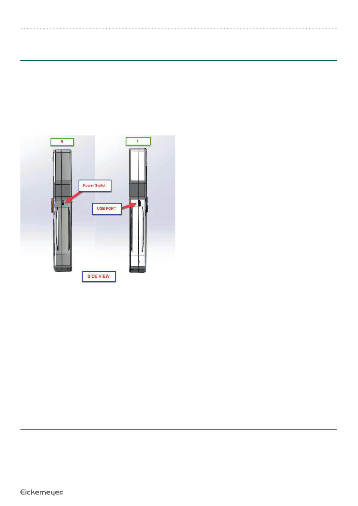
3.1 Power-up
Install batteries
Slide up power switch to power on position.The LCD display should come on and read “*reader ready* ISO/ FECAVA/AVID”, and
the reader should emit two high tones. The reader is now ready for operation.
If the display reads “Low Battery” and the reader emits a single low tone, either the battery is low. If the battery is low, the
reader will still function, but the reading distance will be reduced and the batteries should be replaced. When the batteries
are exhausted, the LCD display will fade and the reader will no longer function.
3.2 Reading ID Tags
To read an ID tag with the Multiscan Microchip Reader, position the reader as close as possible to the location (or suspected
location) of the ID tag, press the read switch, and search for the tag with a slow rotary motion of the read antenna until an ID
is found or until you decide to abandon searching for the tag.
The read switch is a momentary switch: as long as you press it, the reader will be seeking an ID tag.
During the time the reader is looking for an ID tag, the LCD display will read “Scanning…”. When the reader locates and reads
an ID tag, it will display the ID number and sound two high-pitched beeps.
When you let go of the read switch:
• If the reader has displayed a tag number, it will continue to display the number until you press the read switch again to
look for a new tag.
• If the reader has not located an ID tag, it will sound a low-pitched single beep, and the LCD display will show “No ID
Found”.
To preserve battery life, only press the read switch when you are actively looking for an ID tag.
The display shows the following messages:
*Ready Ready* Displayed when reader is fi rst turned ON and battery is OK.
SCANNING… Displayed when seeking an ID tag.
No ID Found Displayed after termination of looking when no valid tag is read.
Low Battery Displayed when low battery is sensed, either when the unit is switched ON or instead of
“Scanning…” when the read switch is pressed down.
AVID*123*456*789 Sample display for a valid AVID tag.
999123456789012 Sample display for a valid ISO tag.
0000000001 Sample display for a valid FDX-A tag.
The read antenna, shown in the picture on page 5, is the interface between the reader and the ID tag.The read antenna emits
a low frequency RF electromagnetic signal to activate the ID tag and read the code in them.
If you understand how the tag interacts with the read antenna, you will be able to save time and obtain the optimum reading
range for each type of ID tag.
The orientation of the reader antenna to the implant affects the range and ability to read. In order to get a good read, the
implant must either be:
• Parallel to the reader antenna.
or
• Pointing at the corner of the reader antenna.
This behavior is a result of the intrinsic nature of underlying technology. Therefore good reading technique is important for
getting reliable reading performances.