© Edwards Limited 2009. All rights reserved. Page 3
Edwards and the Edwards logo are trademarks of Edwards Limited.
INSTALLATION
D059-14-880 Issue D
3 INSTALLATION
3.1 Unpacking and inspection
Remove all packing materials and protective covers and check the IS16K for damage. If the IS16K is damaged, notify
your supplier and the carrier in writing within three days; state the Item Number of the IS16K together with your
order number and your supplier's invoice number. Retain all packing materials for inspection. Do not use the IS16K.
3.2 General
The vacuum switch should be mounted as close as possible to the point at which the pressure is to be measured. Use
a short branch tube with an internal diameter no less than that of the switch vacuum connection. Long, narrow and
angled connections can cause significant errors.
This equipment is not protected from dripping water from above, unless mounted with the vacuum flange pointing
downwards.
3.3 Connection to the Vacuum System
The vacuum switch may be mounted in any orientation but mounting with the vacuum switch vertical will prevent
the possibility of debris falling into the vacuum port and affecting the performance of the switch.
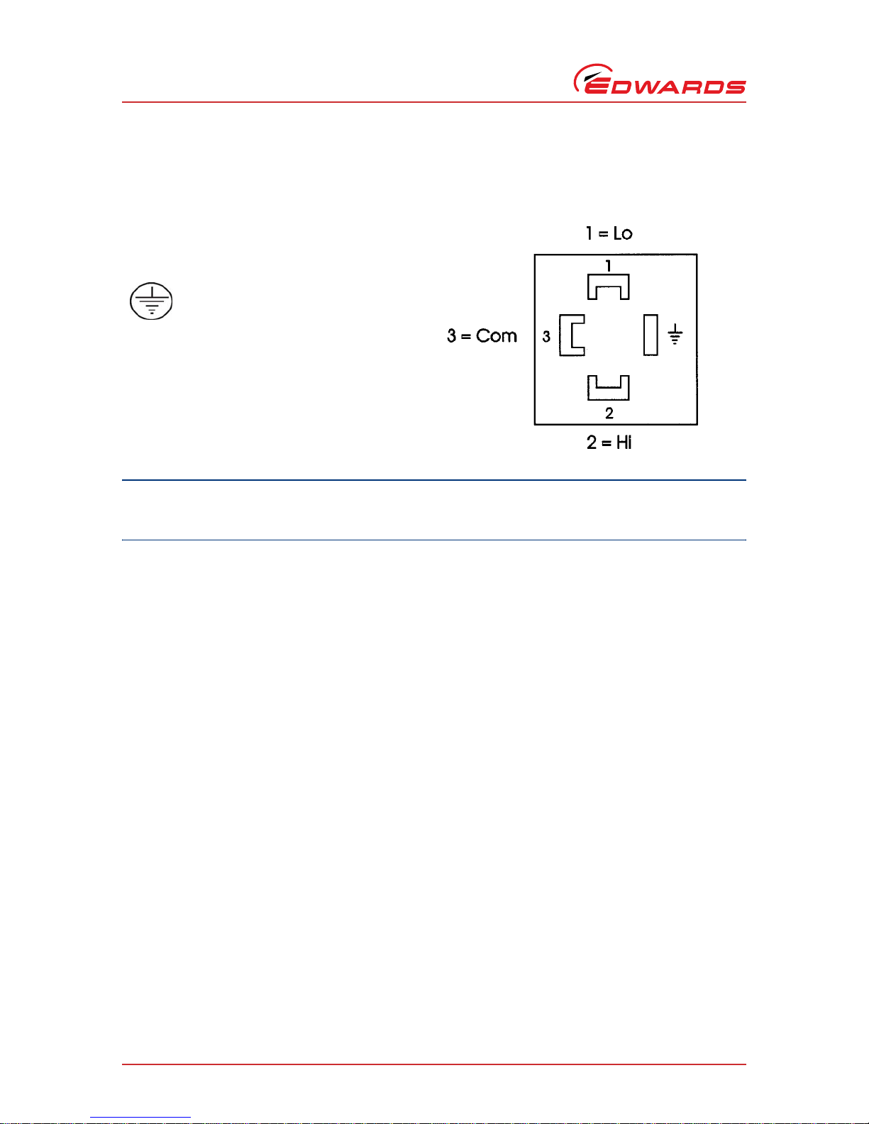
3.4 Connection to the Electrical Circuit
CAUTION
Ensure that the circuit connected to the vacuum switch is suitably fused to prevent the switch contact rating
being exceeded. The fuse rating must not exceed 10 amps.
WARNING
Do not allow the internal pressure to be higher than 1 bar gauge (2 bar absolute). If the pressure
in your system can be higher than 1 bar gauge, you must fit a suitable pressure relief valve.
Overpressure of the switch could cause injury to persons.
WARNING
Ensure that the electrical installation of the Vacuum Switch conforms with your local and national
safety requirements. It must be connected to a suitably fused and protected electrical supply and
a suitable earth point.
WARNING
If, in your application, failure of this switch could lead to a safety hazard, it is recommended that
the switch should be wired in series with another interlocking device, for example chamber lid
microswitch, to provide a double level of protection.