ECO Charge BMM Manuel utilisateur

Battery Monitoring
Module (BMM)
Operator / Installer Manual

2
WARNINGS
Keep open flames
away from batteries
on charge.
Risk of battery
explosion.
Be aware of
battery fumes
and electrolyte.
Do not dispose
of batteries in
the garbage.
Electrical hazard
exists inside the
charger, do not
remove the
side cover.
Always recycle lead
acid batteries.
Battery electrolyte
is highly corrosive.
Wear eye protection
when working near
batteries.

3
Contents
Warnings ....................................................................................................................................... 2
Contents ........................................................................................................................................ 3
Overview ....................................................................................................................................... 4
Installation .................................................................................................................................... 5
Configuration .............................................................................................................................. 8
Operation ....................................................................................................................................11
LED Function Indicator ........................................................................................................11
Voltage Imbalance Monitoring ......................................................................................... 12
Water Level Monitoring ........................................................................................................13
Troubleshooting ......................................................................................................................14
Maintenance ..............................................................................................................................15
Service & Warranty ................................................................................................................16
Specifications ............................................................................................................................17
BMM Serial Number
BMM Part Number
Date Supplied
Battery Model
Purchaser
Purchase Invoice Number
Fleet Number

4
Overview
13
4
5
7
6
1
2
3
4
DC Supply Terminals
Tri-color LED
Temperature Sensor
Communications Toroid
6
5
7
Electrolyte Sensor
Midpoint Voltage Sensor
Module Housing
Battery Monitoring
Module (BMM)
2
This guide covers the installation of a BMM and configuration of a BMM
and associated XHF Series Charger. For instructions on the advanced
functionality of the BMM data logging and analysis features available in the
Charger Interface Software Manual, contact your EcoCharge dealer.

5
Installation
NOTE: Before attempting installation, please read through the complete
installation instructions. The battery to be fitted should be disconnected from
any load prior to installation.
Communications and
Current Sensing Toroid
The Communications Toroid
requires the negative lead to
be removed from the battery
and placed through the toroid
and re-secured to the negative
battery terminal. Alignment of
the toroid should be made so
that the cable exits the toroid
away from the battery terminal.
Keep at least 8in (20cm)
clearance between the toroid
and the positive battery lead. A
half-sleeve on the toroid housing
is provided to secure the toroid
to the battery cable by cable tie.
Unit Location
The BMM module is designed
to sit directly on top of the
battery surface. For optimum
Bluetooth®range, locate the
module near any openings in
the battery enclosure. Cable ties
are supplied to secure the unit
to the battery straps as shown.

6
DC Supply & Voltage
Midpoint Sensor
The DC Supply wires are
terminated with ring terminals
for easy fastening to the
battery with the supplied
screws. The positive (RED) and
negative (BLACK) wires should
be fastened to the top of their
respective battery terminal
posts. The Midpoint Voltage
(WHITE) wire should be
fastened to strapping or a
terminal as close as possible
to the voltage midpoint of
the battery. It is recommended
to coat wire terminations
with corrosion inhibitor before
installation.
Temperature Sensor
The ideal location for the BMM
temperature sensor is between
the cells at the center of the
battery. Depending on the
battery type and construction,
this may not be practical. The
alternative location is cable tied
to the underside of a segment
of lead strapping. An additional
temperature sensor is built-in to
the BMM module.
Installation - continued

7
1
2
3
Electrolyte Sensor
Installation of the electrolyte sensor requires care and consideration of the cell’s
internal construction. If not required, the electrolyte sensor should be removed from
the BMM by cutting the brown sensor wire at the entry point to the BMM module.

8
Configuration
BMM Configuration
Before use, both the BMM and the charger require configuration to enable
the Automatic Profile Configuration (APC) feature.
The following instructions cover:
1. Connecting to the charger
2. Configuring the BMM with the correct battery rating details.
(see page 9).
3.Configuring the charger to enable APC functionality (see page 10).
This step applies to all chargers intended to be used with the BMM.
Required for configuration:
• The BMM installed on the battery.
• A XHF Series Charger
• Standard-A to Mini-B USB cable.
• PC or laptop running Windows Vista or later with Charger
Interface software v7.4 or later.
• Password for BMM configuration
access.
1. Setup Communication via
Charger Interface
• Connect the BMM-equipped
battery to any XHF Series
charger, connect the charger to
the PC via USB and open the
Charger Interface software.
• From the Connection menu,
ensure the appropriate COM port
is selected for the USB interface.
• Verify communications with the
charger by selecting Read Default
9
Configuration.
- If successful, the Voltage and Current details will populate the data
fields.
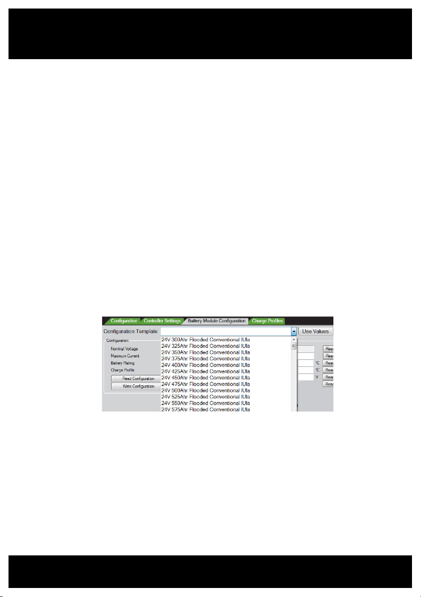
2. Program BMM with Configuration Parameters
• Enable the Battery Module Configuration tab from the Battery Module
menu.
• From the Battery Module Configuration tab, choose the appropriate
battery type from the template drop-down list. Click Use Values to
populate the parameter fields with the template’s parameters.
• To load the configuration parameters into the BMM module, click Write
Configuration.
• The BMM configuration can be confirmed by clicking Read
Configuration, and checking that the correct values are returned
to the parameter fields.
3. Create a BMM Identifier
The BMM should be given a unique name which allows quick identification
of the battery when reading charge logs.
• Enter a unique name in the Identification field
• Click Write to program the BMM with the new name.
- A useful name may include any combination of the site location,
truck ID, or battery ID numbers.

10
Charger Configuration
Configuration of your XHF Series charger for Automatic Profile
Configuration (APC) can be achieved by configuration via the Charger
Interface Software.
• Connect your PC to the charger via USB and ensure the charger has AC
supply.
• Check that the Charger Interface is communicating with the charger by
following the Setup steps on page 8.
• From the Charger menu, enable the Configuration tab, and ensure the
tab is visible.
• From the Configuration Template drop-down list, choose the option
“APC Enabled”.
• Ensure the adjacent drop-down lists are appropriate for charger type
and AC supply.
• Click the Use Values button to populate the parameter fields below.
•
Click Write Default Configuration to program the charger with the
selected parameters.
• Chargers intended for high rate charging should have the additional
parameter “Use Fast Charge Profile” checked, under the Controller
Settings tab.
To confirm successful configuration, the charger front display will read
“APC Enabled”.
Configuration - continued
Table des matières
Manuels Instrument de mesure populaires d'autres marques


Endress+Hauser
Endress+Hauser Proline Promag 50 Caractéristiques techniques

Siemens
Siemens SITRANS F Coriolis FCT030 Manuel de la liste des pièces

KLINGER
KLINGER CMF V Series Manuel utilisateur

EXFO
EXFO FTB-2 Manuel d'exploitation et d'entretien

Keysight
Keysight M8290A Manuel utilisateur

ADTEK
ADTEK MW-5 Manuel utilisateur