Ebyte ME31-XAXX0600 Manuel utilisateur

ME31-XAXX0600
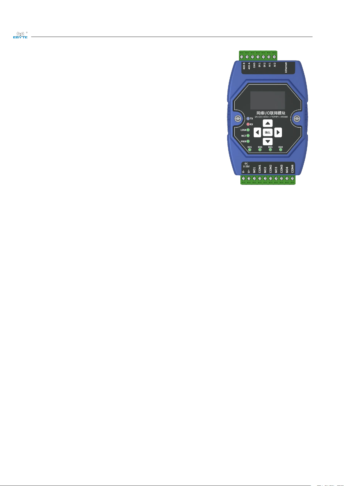
I/O Networking Module

Chengdu Ebyte Electronic Technology Co.,Ltd ME31-XAXX0600_UserManual_CN
Copyright ©2012–2023,Chengdu Ebyte Electronic Technology Co.,Ltd
I
Contents
1. Product overview ........................................................................................................................................................1
1.1 Introduction ...................................................................................................................................................... 1
1.2 Features .............................................................................................................................................................1
1.3 Application typology diagram ..........................................................................................................................2
2. Quick start ...................................................................................................................................................................3
2.1 Devices required ...............................................................................................................................................3
2.2 Device connection ............................................................................................................................................ 3
2.2.1 AI analog input connection ................................................................................................................... 4
2.2.2 Simple use ............................................................................................................................................. 4
2.3 Parameter configuration ................................................................................................................................... 4
2.4 Control test ....................................................................................................................................................... 5
2.4.1 Modbus TCP Control ............................................................................................................................ 5
2.4.2 Modbus RTU Control ............................................................................................................................6
3 Technical indicator ...................................................................................................................................................... 8
3.1Specification and parameter ..............................................................................................................................8
3.2 Device default parameter ................................................................................................................................. 8
3.3 Dimensions .....................................................................................................................................................10
3.4 Ports and indicators ........................................................................................................................................ 11
4 Product function introduction ....................................................................................................................................13
1.4 4.AI input ........................................................................................................................................................13
1.4.1. Analog quantity range ........................................................................................................................ 13
1.4.2. Trigger mode ...................................................................................................................................... 13
1.4.3. Analog input engineering quantity shaping value and engineering quantity floating point value ....14
1.4.4. AI Filtering parameters ...................................................................................................................... 14
4.2 Modbus gateway .............................................................................................................................................14
4.2.1 Modbus TCP/RTU Protocol Conversion ............................................................................................ 14
4.2.2 Modbus address filtering .....................................................................................................................15
4.2.3 Modbus TCP protocol data frame description .................................................................................... 15
4.2.4 Modbus RTU protocol data frame description ................................................................................... 15
4.3 Active upload ..................................................................................................................................................15
4.4Custom Module Information ...........................................................................................................................16
4.4.1 Modbus address ...................................................................................................................................16
4.4.2 Module name .......................................................................................................................................16
4.4.3 Network parameter ..............................................................................................................................16
4.4.4 UART parameter ................................................................................................................................. 17
4.5 OLED display and parameter configuration .................................................................................................. 17
4.5.1 Information display interface .............................................................................................................. 17
4.5.2 Device parameter display interface .....................................................................................................18
4.5.3 Device parameter configuration interface ...........................................................................................18
4.5.4 Screen sleep .........................................................................................................................................19
4.6MODBUS parameter setting ........................................................................................................................... 19
4.6.1 DI register list ......................................................................................................................................19
4.6.2 Module related register ....................................................................................................................... 20

Chengdu Ebyte Electronic Technology Co.,Ltd ME31-XAXX0600_UserManual_CN
Copyright ©2012–2023,Chengdu Ebyte Electronic Technology Co.,Ltd
II
4.6.3 Network related register ......................................................................................................................20
4.6.4 Modbus command operation ...............................................................................................................21
5 Host computer ........................................................................................................................................................... 24
5.1 Acquisition and control .................................................................................................................................. 24
5.2 Parameter Configuration Interface .................................................................................................................25
Revision history ............................................................................................................................................................27
Chengdu Ebyte Electronic Technology Co.,Ltd ME31-XAXX0600_UserManual_CN
Copyright ©2012–2023,Chengdu Ebyte Electronic Technology Co.,Ltd
1
1. Product overview
1.1 Introduction
ME31-XAXX0600 features 6 channel analog (0-20mA/4-20mA)
input,supports Modbus TCP protocol or Modbus RTU protocol for
acquisition and control and can be used as a simple Modbus gateway
(automatically send commands with non-local Modbus addresses through
the serial port/network port).
1.2 Features
Good for standard Modbus RTU protocol and MODBUS TCP protocol;
Work with various configuration software/PLC/touch screen;
RS485 acquisition control I/O;
RJ45 acquisition control I/O,support 4 channel master access;
Support OLED display screen to display status information, and device parameters can be configured through
buttons;
6 channel analog (0-20mA/4-20mA)input;
Support custom Modbus address settings;
Support 8 common baud rate configurations ;
DHCP and static IP;
DNS function, domain name analysis;
Support Modbus gateway;
Chengdu Ebyte Electronic Technology Co.,Ltd ME31-XAXX0600_UserManual_CN
Copyright ©2012–2023,Chengdu Ebyte Electronic Technology Co.,Ltd
2
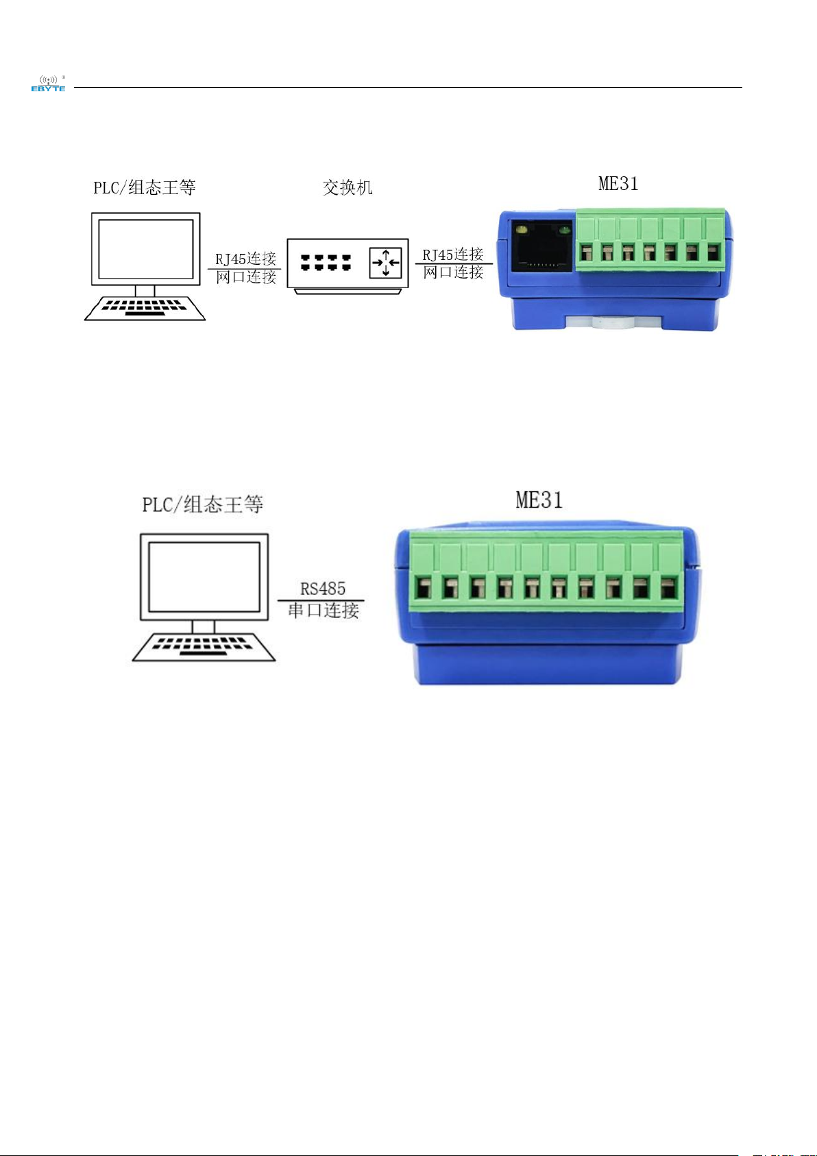
1.3 Application typology diagram
Network port application topology
Serial port application topology

Chengdu Ebyte Electronic Technology Co.,Ltd ME31-XAXX0600_UserManual_CN
Copyright ©2012–2023,Chengdu Ebyte Electronic Technology Co.,Ltd
3
2. Quick start
Note: The test need to carry out with factory parameter.
2.1 Devices required
ME31-XAXX0600
12V SMPS
USB to RS485
Computer
RJ45 Cable
More cables
2.2 Device connection
2.2.1 RS485 connection
Note: When the 485 bus high frequency signal is transmitted, the signal wavelength is shorter than the transmission
line, and the signal will form a reflected wave at the end of the transmission line, which will interfere with the
Chengdu Ebyte Electronic Technology Co.,Ltd ME31-XAXX0600_UserManual_CN
Copyright ©2012–2023,Chengdu Ebyte Electronic Technology Co.,Ltd
4
original signal. Therefore, a terminal resistance must be added at the end of the transmission line to prevent the
signal from being reflected after reaching the end of the transmission line. The terminal resistance should be the
same as the impedance of the communication cable, with a typical value of 120 ohms. Its function is to match the
bus impedance and improve the anti-interference and reliability of data communication.
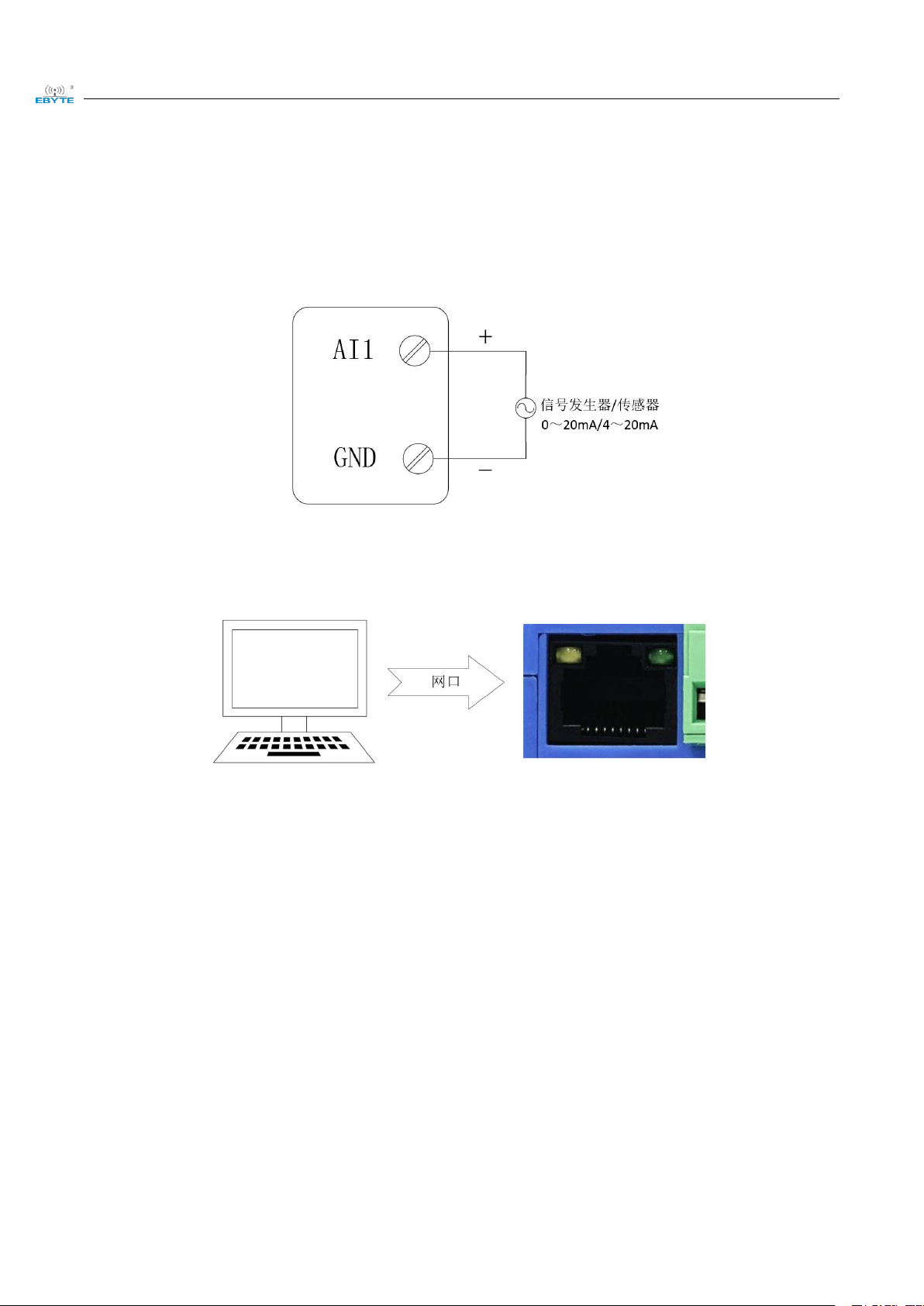
2.2.1 AI analog input connection
2.2.2 Simple use
Wiring: The computer is connected to the RS485 interface of ME31-XAXX0600 through USB to RS485, A is connected to A, B is connected to B.
Networking: Insert the network cable into the RJ45 port and connect to the PC.
Power supply: Use DC-12V switching power supply (DC 8~28V) to supply power to ME31-XAXX0600.
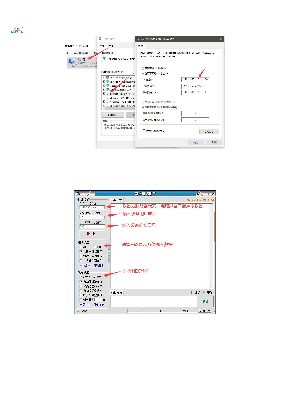
2.3 Parameter configuration
Step 1: Modify the IP address of the computer to be consistent with the device. Here it is modified to 192.168.3.100
to ensure the same network segment as the device and that the IP is different. Please turn off the firewall and try
again if the step failed;
Chengdu Ebyte Electronic Technology Co.,Ltd ME31-XAXX0600_UserManual_CN
Copyright ©2012–2023,Chengdu Ebyte Electronic Technology Co.,Ltd
5
Step 2: Open the network assistant, select the TCP client, enter the remote host IP192.168.3.7 (default parameters),
enter the port number 502 (default parameters), and select HEX to send.
2.4 Control test
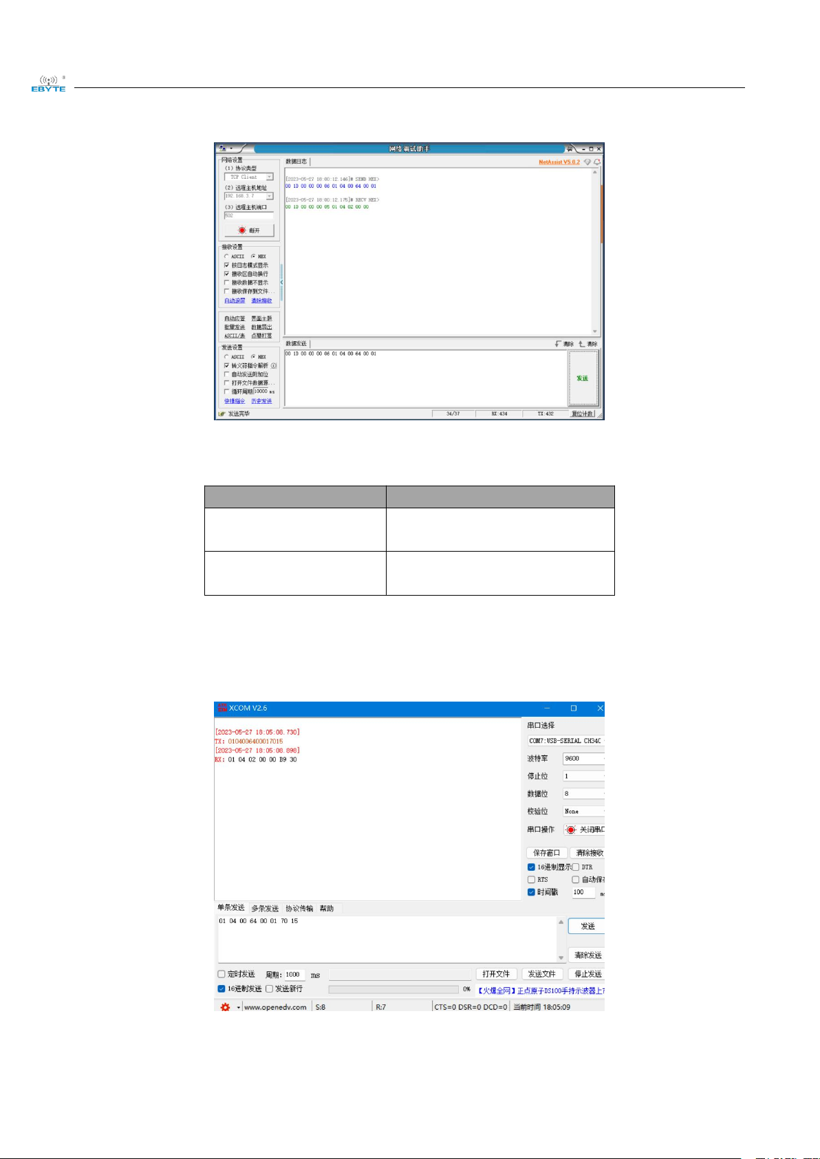
2.4.1 Modbus TCP Control
Use network assistant to read l ME31-XAXX0600, collected first channel AI data.
Chengdu Ebyte Electronic Technology Co.,Ltd ME31-XAXX0600_UserManual_CN
Copyright ©2012–2023,Chengdu Ebyte Electronic Technology Co.,Ltd
6
Please note that unit of read value is uA.
To test other function according to below table
Function (function code)
Command
Read AI first channel
collected value(0x04)
00 1D 00 00 00 06 01 04 00 64 00
01
Read AI all collected value
(0x04)
00 1F 00 00 00 06 01 04 00 64 00
06
2.4.2 Modbus RTU Control
Use network assistant to readl ME31-XAXX0600, first channel AI collected data.
To test other function according to below table

Chengdu Ebyte Electronic Technology Co.,Ltd ME31-XAXX0600_UserManual_CN
Copyright ©2012–2023,Chengdu Ebyte Electronic Technology Co.,Ltd
7
Function (function code)
Command
Read AI first channel
collected value(0x04)
01 02 04 00 64 00 00 08
79 CC01 70 15
Read AI all collected value
(0x04)
01 04 00 64 00 06 31 D7
Table des matières
Autres manuels Ebyte Système d'E/S


