DLX ASAP-HUB Manuel utilisateur

//
//
© 2021 DLX ENTERPRISES LLC. // VERSION 1.02 PROUDLY MADE IN THE USA. // CAGE CODE: 7CFK2 // DUNS #: 079751064 // SBA 8(a) CERTIFIED
ENGLISH MANUAL

//
//
//
© 2021 DLX ENTERPRISES LLC. // VERSION 1.02
//
TITLE HERE TITLE HERE
1 1
// LIMITED WARRANTY //
At Deployed Logix we’re redefining rapid deployment. Through our extensive
work with law enforcement, search and rescue teams, various first responders,
private organizations both domestically and abroad, and the military, our team
understands that when a crisis calls, seconds count. Discover why we are the
leader in American-made, rapidly deployable disaster preparedness products.
Your Deployed Logix handmade quality products are covered by a three-year
limited warranty. The limited warranty does not cover small imperfections due,
in part, to the production of handmade products. Any imperfections must be
limited and not inhibit the performance of the product. The limited warranty
is restricted to the repair or replacement of any part which proves to be
defective, at the discretion of Deployed Logix, and the claim must be made
in writing prior to the warranty’s expiration date. Deployed Logix will repair or
replace any component deemed to be faulty from manufacturing in the most
efficient and timely means available.
The limited warranty on workmanship is limited to defects at the time
of manufacturing and does not cover general wear, tear, or misuse of the
product. The warranty does not cover damage caused by abuse, misuse,
neglect, or improper care by the end user in the application of the Deployed
Logix product.
The products and/or components not manufactured by Deployed Logix
shall be subject only to the warranty extended by the original manufacturer.
Component manufacturer warranties may exceed that of Deployed Logix. No
warranty is made or implied regarding the intended use of the product.
Deployed Logix must authorize all claims prior to any action taken by the
end user. No items shall be returned for warranty repair without prior written
authorization from Deployed Logix. For replacement of products damaged
from general use and time please contact Deployed Logix in reference to the
“Buy Back Program.”
For immediate attention regarding any defective product, please phone
Customer Support at +1-541-357-5978, 8:00 AM – 5:00 PM, USA Pacific Time.
*This warranty does not cover marks, scuffs, or abrasions that might allow
light to pass through the blackout vinyl.
ASAP-HUB®
1
ASAP-HUB®SHELTER ARCH COMPONENTS
ASAP-HUB®CENTER & SUPPORT COMPONENTS
RIDGE SUPPORT
BAR
A
B
x4
x1
x2
®
ASAP-HUB
CENTER SUPPORT
ASSEMBLY
ARCH
ASSEMBLY
x2
RIDGE SUPPORT
BAR
FOOT PLATE
x4
SHELTER LEG
x4
SHELTER LEG
x2 x2
ARCH
ASSEMBLY

//
//
//
//
© 2021 DLX ENTERPRISES LLC. // VERSION 1.02 2
CENTER
DRAIN INSTALLATION DRAIN PUMP INSTALLATION
ROOF INSTALLATION SPRAYER ADJUSTMENT
ARCH SECTION SETUP ARCH SECTION SETUP
1 2
Retrieve arch sections from labeled frame bags. Swing joints and pin
in place. Be sure to orient pins toward interior of shelter to prevent
pin extraction.
Retrieve ridge support bars from labeled frame bags. Insert into
socket with label A facing up. Pin in place. Connect arms along
frame making sure angle points to center. Label B should align with
each other.

//
//
//
© 2021 DLX ENTERPRISES LLC. // VERSION 1.02
//
3
LABEL UP!
BOLT SHOULD FACE DOWN
DRAIN INSTALLATION DRAIN PUMP INSTALLATION
SPRAYER ADJUSTMENT
CENTER FRAME SETUP SHOULDER SUPPORT BARS
3 4
Position center frame section in desired location. Lift and connect
arch sections in a clockwise or counterclockwise rotation. Pin in
place with cable underneath frame.
Connect shoulder support bars. Orient support bar so that the Label
D faces up. Insert pin down into socket to secure.

//
//
//
//
© 2021 DLX ENTERPRISES LLC. // VERSION 1.02 4
DRAIN INSTALLATION DRAIN PUMP INSTALLATION
ROOF INSTALLATION SPRAYER ADJUSTMENT
INSULATION INSTALLATION INSULATION INSTALLATION
5 6
IF NOT UTILIZING INSULATION, SKIP TO STEP 8.
Locate centerline of insulation liner, connect snap clips to center
point on cables, then attach loops along centerline frame.
Connect insulation liner along opposite ridge line.

//
//
//
© 2021 DLX ENTERPRISES LLC. // VERSION 1.02
//
5
x8
DRAIN INSTALLATION DRAIN PUMP INSTALLATION
INSULATION INSTALLATION ROOF COVER INSTALLATION
7 8
Connect insulation liner around remaining perimeter of shelter
framework. Each quadrant of the shelter will have a minimum of four
(4) attachment points (BLACK ARROWS) for a total of sixteen (16)
perimeter attachment points.
Retrieve roof cover. Unfold starting at one side. Unroll to opposite
side. Place grommet onto post. Connect pins at provided locations
with open end facing out.

//
//
//
//
© 2021 DLX ENTERPRISES LLC. // VERSION 1.02 6
!
!
LIFT TWO ADJACENT CORNERS
SIMULTANEOUSLY TO MINIMIZE
STRESS ON FRAME JOINTS
2 PERSON MIN. 3 PERSON OPTIMUM
BEGIN AT PEAK
DRAIN INSTALLATION DRAIN PUMP INSTALLATION
ROOF INSTALLATION SPRAYER ADJUSTMENT
ENDWALL ATTACHMENT LEG ATTACHMENT
910
Attach endwalls. Begin attachment at peak of shelter and work
outward from center connecting hook and loop strips.
NOTE: Endwalls can be attached once shelter is fully erected.
Lift shelter one half first. Using four (4) personnel, lift at two corners
and attach two (2) legs per corner. Once first half is erected, repeat
step on opposite half.

//
//
//
© 2021 DLX ENTERPRISES LLC. // VERSION 1.02
//
7
CONNECT LANYARD
DRAIN INSTALLATION DRAIN PUMP INSTALLATION
FOOT ATTACHMENT ENDWALL / INSULATION ATTACHMENT
11 12
Connect shelter footpads. Align posts with socket on leg segments,
secure using pins with open end facing inward. Connect lanyards
around 4 base sides.
Complete connection of endwall hook and loop strips along vertical
portion of shelter. If insulation was utilized during setup, complete
attachment of loops to shelter frame segments at corner.

//
//
//
//
© 2021 DLX ENTERPRISES LLC. // VERSION 1.02 8
FOLD DOWN SKIRTS
CONNECT INTERIOR BUCKLES
POSITION FLOOR
UNDERNEATH FOOTPLATE
DRAIN INSTALLATION DRAIN PUMP INSTALLATION
FLOOR ATTACHMENT FOLD DOWN SKIRTS
13 14
Layout floor gray side up and position so the reinforced vinyl
segment aligns with each corner of the shelter frame. Fold up
floor and connect hook and loop strips on floor to matching strips
underneath endwall skirts.
Fold down skirts on endwalls and corner cover to deflect rain run-
off away from seams. Connect buckle on interior of shelter at each
corner.
//
//
//
© 2021 DLX ENTERPRISES LLC. // VERSION 1.02
//
9
~4 ft
DRAIN INSTALLATION DRAIN PUMP INSTALLATION
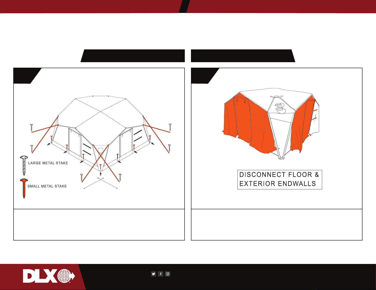
STAKING SHELTER STRIKE
! 1
SHELTER MUST BE STAKED & SECURED AT ALL TIMES WHEN
ERECTED. FAILURE TO SECURE STRUCTURE COULD RESULT IN
DAMAGE TO EQUIPMENT OR SERIOUS PERSONAL INJURY!
Begin strike of shelter by removing all installed accessories. Discon-
nect all power sources and climate control systems. Start by remov-
ing and folding endwalls. Folding instructions are provided at Step
10.
Table des matières
Autres manuels DLX Abri

Manuels Abri populaires d'autres marques


Storage Canopy
Storage Canopy C3340R Manuel utilisateur

Frabill
Frabill ICE HUNTER 195 Manuel utilisateur

Shelters4Less
Shelters4Less SR1588 Manuel utilisateur

Sealey
Sealey Power Products GSS150819SD Manuel utilisateur

Crivit
Crivit 104155 Manuel utilisateur

No Butts Bin
No Butts Bin SR1558-F Manuel utilisateur