Distech Controls ECx-400 Series Manuel utilisateur

ECx-400 UUKL Extension Modules
Figure1: ECx-400 UUKL model
Product Description
This document describes the hardware installation procedures for the ECx-400 Series I/O Extension Modules.
The Distech Controls ECL-600 and ECB-600 Series controllers product line is designed to control and monitor various HVAC equipment such as roof top
units, large air handling units as well as central plant applications such as chillers and boilers. These controllers are compatible with the I/O Extension
Module product line, which includes the following modules: ECx-400, ECx-410, ECx-420, and ECx-400 UUKL.
This document describes the hardware installation procedures for the ECx-400 UUKL Extension Modules only.
The ECx-400 UUKL I/O Extension module is the only model to be used in the Distech Controls UUKL smoke control system. For detailed
requirements, specifications, and procedures for installing and operating UL 864 Listed equipment, you must refer to the Distech Controls
UUKL Smoke Control System Design Guide (UUKL Design Guide_UG_10_EN). Failure to meet the requirements or follow the procedures in
the Distech Controls UUKL Smoke Control System Design Guide can void the UL 864 Listing for smoke control equipment.
These I/O Extension Modules are all built on a similar platform, but have different numbers of inputs and outputs. Moreover, each individual
model has different amounts of digital and/or universal outputs. For more information on the specific layout and functionality of each I/O
Extension Module, please refer to the ECB-600 datasheets.
General Installation Requirements
For proper installation and subsequent operation of the device, pay special attention to the following recommendations:
£It is recommended that the controller(s) be kept at room temperature for at least 24 hours before installation to allow any condensation that may
have accumulated due to low temperature during shipping/storage to evaporate.
£Upon unpacking, inspect the contents of the carton for shipping damages. Do not install a damaged device.
£The device is designed to operate under environmental conditions that are specified in its datasheet.
£Ensure proper ventilation of the device and avoid areas where corroding, deteriorating or explosive vapors, fumes or gases may be present.
£Allow for proper clearance around the device’s enclosure and wiring terminals to provide easy access for hardware configuration and maintenance.
£When installing in an enclosure, select one that provides sufficient surface area to dissipate any heat generated by the device and by any other de-
vices installed in the enclosure. A metal enclosure is preferred. If necessary, provide active cooling for the enclosure.
£Orient the controller with the ventilation slots and power supply/output terminal block connectors towards the top to permit proper heat dissipation.
£The device’s plastic enclosure has a back plate that is separable from the front plate allowing the back plates (with the connectors) to be shipped di-
rectly to the installation site while all the engineering is done in the office.
£The device’s datasheet specifies the power consumption (amount of heat generated), the operating temperature range, and other environmental
conditions the device is designed to operate under.
£Ensure that all equipment is installed according to local, regional, and national regulations.
£Do not drop the device or subject it to physical shock.
£If the device is used and/or installed in a manner not specified by Distech Controls, the functionality and the protection provided by the device may
be impaired.
Installation Guide

2 / 16
Any type of modification to any Distech Controls product will void the product’s warranty
Take special care to keep the front and back plate aligned when separating and joining them.
Take reasonable precautions to prevent electrostatic discharge to the device when installing, servicing or during operation. Discharge
accumulated static electricity by touching one’s hand to a well-grounded object before working with the device.
Device Markings (Symbols)
Certain markings (symbols) can be found on the controller and are defined as follows:
Symbol Description
CE marking: the device conforms to the requirements of applicable EC directives.
Products must be disposed of at the end of their useful life according to local regulations.
Read the Hardware Installation Guide for more information.
UL marking: conforms to the requirements of the UL certification.
FCC marking: This device complies with FCC rules part 15, subpart B, class B.
Warning Symbol: Significant information required. Refer to the Hardware Installation Guide.
Alternating Current
Direct Current
General Wiring Recommendations
Risk of Electric Shock: Turn off power before any kind of servicing to avoid electric shock.
£All wiring must comply with electrical wiring diagrams as well as national and local electrical codes.
£To connect the wiring to a device, use the terminal connectors. Use a small flat screwdriver to tighten the terminal connector screws once the wires
have been inserted (strip length: 0.25’’ (6mm), tightening torque 0.5 Nm).
£Comply with all network and power supply guidelines outlined in the Network Guide.
£Always use unshielded cabling with a minimum Category 5 (CAT5) cable for ethernet communications.
£Keep wiring separate according to their function and purpose to avoid any ambient noise transmission to other wires. Use strapping to keep these
wires separated. For example, keep power, hazardous voltage, SELV, PELV, network, and input wiring separate from each other.
£The board connectors accept wires or flat cables ranging from 22 to 14AWG (0.644 to 1.630mm diameter) per pole. However, power cables must be
between 18 and 14AWG (1.024 to 1.630mm diameter).
£Keep all wires away from high speed data transmission cables (for example, Ethernet, etc.).
£Do not connect the universal inputs, analog/digital outputs or common terminals to earth or chassis ground (unless stated otherwise).
£Keep input and output wiring in conduits, trays or close to the building frame if possible.

3 / 16
I/O Extension Module Dimensions & Components
Figure2: Rear view of large enclosure
Figure3: Side view of large enclosure

4 / 16
Mounting Instructions
The controller can be mounted on a DIN rail to speed up the installation procedure. They are also equipped with two mounting holes 0.25” x
0.165” (6.35mm x 4.191mm). The I/O Extension module can be mounted in a panel or on a wall by using appropriate screw types (use sheet metal,
thread forming, or self-tapping screws accordingly).
The controller’s mounting orientation must be horizontal with controller’s back attached to a vertical wall surface.
Figure4: Permitted Mounting Positions
DIN Rail-Mounted Installation
1. Ensure the DIN rail is properly mounted on the wall.
2. Simply clip controller onto the DIN rail.
Wall-Mounted Installation
3. Open the enclosure by separating the front and back plate while pressing on the side clips.
4. Use the back plate’s mounting holes to mark the location of any holes that need to be drilled.
5. Drill the holes.
6. Clean the surface and mount the controller using the appropriate screw types.

5 / 16
Power Wiring
Voltage for UUKL models: 24VAC; ± 15%, Class 2
Voltage for all non-UUKL models: 24VAC/DC; ± 15%, Class 2
This is a Class 2 Product. Use a Class 2 transformer only (rated at 100VA or less at 24VAC) to power the
controller(s).
The Network Guide provides extensive information and requirements for powering a controller. It can be downloaded from our website. For the UUKL ex-
tension module, refer to the Distech Controls UUKL Smoke Control System Design Guide.
It is recommended to wire only one controller per 24VAC transformer.
If only one 24VAC transformer is available, determine the maximum number of controllers that can be supplied using the following method to determine
the required power transformer capacity:
£Add up the maximum power consumption of all controllers including external loads and multiply this sum by 1.3.
£If the resulting number is higher than 100VA, use multiple transformers.
Use an external fuse on the 24VAC side (secondary side) of the transformer, as shown below, to protect all controllers against power line spikes.
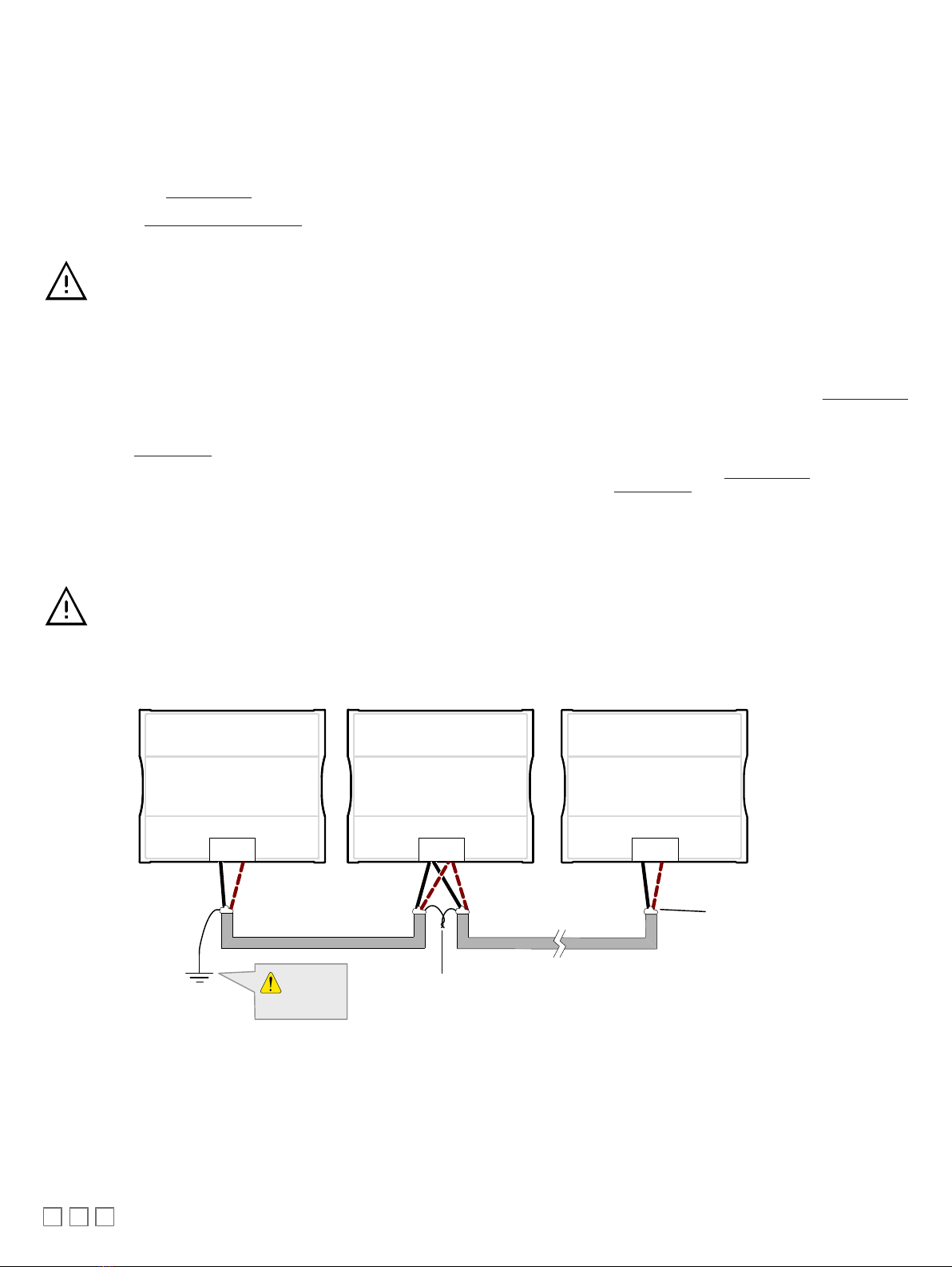
Maintain consistent polarity when connecting controllers and devices to the transformer. One terminal on the secondary side of the transformer must be
connected to the building’s ground. All 24V COM terminals of all controllers and peripherals throughout the LAN or the Subnetwork network must be con-
nected to the grounded transformer terminal as shown below. This ensures that the 24V COM terminals of all devices connected to any LAN or Subnet-
work in the building are at the same potential.
A mechanical ground is unacceptable: Do not use a pipe, conduit, or duct work for a ground. The power supply must
have a dedicated ground wire that comes from the main electrical supply panel.
Failure to maintain consistent polarity throughout the entire network will result in a short circuit and/or damage to the
controller!
The COM terminals of the controller are internally wired to the 24V COM terminal of the power supply. Connecting a
peripheral or another controller to the same transformer without maintaining polarity between these devices will
cause a short circuit.
Controller 2 Transformer
Controller 1
AC
24V AC
24V COM
Fuse: 4 A Max.
Fast Acting
24 VAC
Electrical System Ground
- At Transformer Only
24V AC
24V COM
Figure5: Power wiring – AC
Controller 2
Controller 1
24V AC/DC
24V COM
Fuse: 4 A Max.
Fast Acting
Electrical System Ground
- At Power Supply Only
24V AC/DC
24V COM 24 VDC
Figure6: Power wiring – DC (for all non-UUKL model only)

6 / 16
Input Wiring
Before connecting a sensor to the controller, refer to the installation guide of the equipment manufacturer.
£For a wire length less than 75’ (23m), either a shielded or unshielded 18AWG wire may be used.
£For a wire up to 200’ (61m) long, a shielded 18AWG wire is recommended.
£The shield of the wire should be grounded on the controller side only and shield length should be kept as short as possible.
Input can be connected as follows. Table 1 shows the input designation for the ECx-400 UUKL I/O Extension Module.
Sensor Input Type Input Des-
ignation
Input Connection Diagram
£Dry Contact input.
£Pulsed input
UIx
UIx
COM
To Digital
Input
Digital Dry Contact
NO-NC
£RTD input (for example, 1000Ω).
£Thermistor Input (for example, 10kΩ type II and III).
UIx
UIx
COM
To Analog-
To-Digital
Converter
RTD/
Thermistor
£Resistive input, (for example, use with 10kΩ and 100kΩ potentiome-
ters).
UIx
UIx
COM
To Analog-
To-Digital
Converter
Potentiometer
10kΩ
£0 to 20mA input used with a 2-wire, 0 to 20mA sensor powered by the
ECx-400 UUKL internal 15VDC power supply.
UIx
+
-
Sensor 0-20mA Controller
0-20mA Input
Equivalent
Circuit
UIx
COM
To Analog-
To-Digital
Converter
249Ω
Jumper
Setting
0-10V
0-20mA
+15VDC
£0 to 20mA input used with a 2-wire, 0 to 20mA sensor powered by an
external 24VDC power supply.
UIx
-
+
Sensor
0-20mA Controller
0-20mA Input
Equivalent
Circuit
UIx
COM
To Analog-
To-Digital
Converter
249Ω
Jumper
Setting
0-10V
0-20mA
24VDC
£0 to 20mA input used with a 3-wire, 0 to 20mA sensor powered by an
external 24VAC power supply.
UIx
AC
+
Common
Sensor 0-20mA Controller
0-20mA Input
Equivalent
Circuit
UIx
COM
To Analog-
To-Digital
Converter
249Ω
Jumper
Setting
0-10V
0-20mA
24VAC
£0 to 20mA input used with a sensor powered by its own power source. UIx
+
-
Sensor
0-20mA Controller
0-20mA Input
Equivalent
Circuit
UIx
COM
To Analog-
To-Digital
Converter
249Ω
Jumper
Setting
0-10V
0-20mA
£Voltage input used with a 3-wire 0 to 10VDC or 0 to 5VDC sensor
powered by an external 24VAC power supply
UIx
AC
+
Common
0-10V
Sensor
UIx
COM To Analog-
To-Digital
Converter
24VAC
£Voltage input used with a 0 to 10VDC or 0 to 5VDC sensor powered
by its own power source.
UIx
+
-
0-10V
Sensor
UIx
COM
To Analog-
To-Digital
Converter

7 / 16
Sensor Input Type Input Des-
ignation
Input Connection Diagram
£Slow Pulse – Internal supply: 2-wire pulse meter, maximum input fre-
quency of 1Hz (500ms minimum ON/OFF)
£Connect the pulse input according to the figure for a pulse meter that
can pull-down a +5VDC supply with a 10KΩ pull-up resistor (internal
supply type).
UIx
Pulse Meter
Output
Controller
Pulse Input
Equivalent
Circuit
UIx or DIx
COM To Pulse Count
Accumulator
+
-
10KΩ
5VDC
Table1: Input Wiring
Output Wiring
Before connecting an output device (actuator, relay, etc.) to the controller, refer to the datasheet and installation
guide of the equipment manufacturer.
£For a wire length less than 75’ (23m) long, either a shielded or unshielded 18AWG wire may be used.
£For a wire length up to 200’ (61m) long, a shielded 18AWG wire is recommended.
£The shield of the wire should be grounded on the controller side and the shield length should be kept as short
as possible.
Table 2 shows the output designation for ECx-400 UUKL I/O Extension Module.
Control Output Type Output
Designation
Output Connection Diagram
£Discrete 0 or 12VDC digital, Pulse, or PWM output controlling a
12VDC relay.
UOx
From
Digital
Output
12VDC Relay
A1
A2
UOx
COM
£Current 0 to 20mA universal output & jumper configuration UOx
0-20mA
Common
From Digital-To-
Analog Output
UOx
COM
JUMPER
SETTING
0-10V
0-20mA
£Linear 0 to 10VDC digital to analog output. UOx
0-10V
Common
From Digital-
To-Analog
Output
UOx
COM
£0 to 10VDC voltage output controlling an analog actuator that is pow-
ered by an external 24VAC power source.
UOx
0-10V
~ or +
From Digital-
To-Analog
Output
UOx
COM
Actuator
or -
24VAC
Table2: Output Wiring
8 / 16
Subnet-Wiring
The subnet is used to connect a range of Allure Series Communicating Sensors:
£The Allure EC-Smart-Vue sensor is a communicating room temperature sensor with backlit display graphical menus and VAV balancing capabilities.
£The Allure EC-Smart-Comfort and Allure EC-Smart-Air Communicating Sensors are a range of communicating room temperature sensors.
Connect the Allure Series Communicating Sensor to the controller’s Subnet Port with a standard Category 5e Ethernet patch cable fitted with RJ-45 con-
nectors. Refer to the Network Guide for extensive information and requirements for the connection of the Allure Series Communicating Sensor. It con-
tains information about network topology and length, cable type, setting the Subnet ID, etc. It can be downloaded from www.distech-controls.com web-
site. See also the Hardware Installation Guide supplied with Allure Series Communicating Sensor.
If you make your own patch cable, see the Allure Series Communicating Sensor Hardware Installation Guide.
Protect the controller’s connector from being pulled on when a cable to Allure Series Communicating Sensor is
connected. Create a strain-relief by looping the cable and attaching it to a solid object with a nylon tie so that a tug on
the cable will not pull out the connector on the controller.
Communications Wiring
ECx-400 UUKL IO Extension Modules are connected to the SUBNET– and SUBNET+ terminals of the ECB-600 UUKL controller. The Network Guide
provides extensive information and requirements to implement the subnetwork for the ECx-400 UUKL I/O Extension Modules. It contains information
about network length, cable type, controller addressing, etc. See the Hardware Installation Guide supplied with the ECx-400 UUKL I/O Extension Mod-
ule. It can also be downloaded from the www.distech-controls.com website. For the UUKL extension module, refer to the Distech Controls UUKL Smoke
Control System Design Guide.
For optimal performance, use Distech Controls 24 AWG (0.65 mm) stranded, twisted pair shielded cable or refer to the Network Guide for cable specifi-
cation. For the UUKL extension module, refer to the Distech Controls UUKL Smoke Control System Design Guide. The subnetwork communication wire
is polarity sensitive and the only acceptable topology is to daisy-chain the cable from one I/O Extension Module to the next.
As shown below:
£The first and last daisy-chained subnetwork device must have its EOL resistors enabled / in-
stalled. All other devices must have their EOL resistor disabled (default factory setting).
£When the subnetwork data bus is connected to a following device, twist data bus shields to-
gether.
£Isolate all shields with electrical tape so there is no exposed metal that can touch ground or other
conductors.
£The shield of the data bus must be connected to the electrical system ground at only one point –
usually at one end of the bus as shown below.
£The I/O Extension Module and the Allure Series Communicating Sensor share the same subnet-
work.
ECB-600
ECL-600
SUBNET +
SUBNET -
SUBNET +
SUBNET -
ECx-4XX ECx-4XX
SUBNET+
SUBNET -
ECx-4XX Sub-
Network Bus
ECx-4XX Sub-
Network Bus
Shield: Isolate
with electrical
tape
ECx-4XX Sub-Network Bus
Shields: Twist together and
Isolate with electrical tape
Data Bus: Shielded
Twisted Pair Cable
Electrical
System
Ground
Figure7: Subnetwork bus shielding

9 / 16
About the Subnetwork Bus
The ECB-600 UUKL controllers use the Subnetwork bus to support the ECx-400 UUKL I/O Extension Modules through the controllers Subnet+ and Sub-
net- terminals with 2-wire shielded cable.
The ECB-600 UUKL controllers also use the Subnetwork bus to support one or more Allure Series Communicating Sensor(s) using standard structural
(Cat 5e) cabling.
Subnetwork Bus Total Length
The total maximum length of all Subnetwork buses, including both the length of the Allure Series Communicating Sensor Subnetwork bus and the
ECx-400 Series Subnetwork bus is 300 m (1000 ft). The maximum length of the Allure Series Communicating Sensor Subnetwork bus is 200 m (650 ft).
The maximum length of the ECx-400 Series Subnetwork bus is 300 m (1000 ft).
Sub-Network Bus Total Length: 300 m (1 000 ft) Maximum
Sub-Network Bus: 200 m
(650 ft) Maximum
Allure EC-Smart-Vue
Sub-Network Bus: 300 m
(1 000 ft) Maximum
ECx-400
Typical Compatible
Controller Extension I/O Modules
ECx-400
Sub-Network Bus - Cat 5e Cable
with RJ-45 Connectors
Allure EC-Smart-Vue
Sub-Network Bus
ECx-400
2-Wire Shielded Cable
Figure8: Subnetwork Bus Overview Showing the Allure EC-Smart-Vue Subnetwork Bus and the ECx-400 Series Subnetwork Bus
Subnetwork Bus Topology and EOL Terminations
When ECx-400 Series I/O Extension Modules are installed with an ECB-600 or ECL-600 Series controller, only the EOL terminations of the ECB-600 /
ECL-600 controller and the last I/O Extension Module are set to ON. All other I/O Extension Modules must have their EOL terminations set to OFF.
EOL OFF
EOL ON
EOL OFF
EOL ON
Typical Compatible
Controller
ECx-4xx
I/O Extension Modules
ECx-4xx
Sub-Network Bus 2 - Wire Shielded
For Compatible Controllers:
Sub-Network EOL is set to ON
-Last daisy-chained I/O Extension Module:
EOL Jumper is ON
-All other I/O Extension Modules:
EOL Jumpers are OFF
Figure9: Setting the EOL Terminations on the Subnetwork Bus
When ECx-400 Series I/O Extension Modules are installed with an ECB-600 or ECL-600 Series controller and with Allure Series Communicating Sen-
sors, only the EOL terminations on the last I/O Extension Module and the last Allure Series Communicating Sensor are set to ON. The ECB-600 /
ECL-600 and all other I/O Extension Modules and Allure Series Communicating Sensor s must have their EOL terminations set to OFF.

10 / 16
EOL OFF
ON
EOL
OFF
EOL ON
Typical Compatible
Controller I/O Extension Modules
ECx-4xx
ECx-4xx
I/O Extension Modules 2 - Wire Shielded
- Last daisy-chained I/O Extension Module:
EOL Jumper is ON
- All other I/O Extension Modules:
EOL Jumpers are OFF
- Last daisy-chained Communicating Sensor:
EOL Jumper is ON
- All other Communicating Sensors:
EOL Jumpers are OFF
Communicating Sensor Sub-Network Bus
- Cat 5e Cable with RJ-45 Connectors
Figure10: Setting the EOL Terminations on the ECx-400 Series Subnetwork Bus when Allure EC-Smart-Vue Sensors are used
ECx-400 Series devices and Allure EC-Smart-Vue sensors are factory-set with the EOL set to OFF by default.
If inserting multiple wires in the terminals, ensure to properly twist wires together prior to inserting them into the terminal connectors.
For more information and detailed explanations on network topology and wire length restrictions, refer to the Network Guide, which can be downloaded
from our website
www.distech-controls.com
. For the UUKL extension module, refer to the Distech Controls UUKL Smoke Control System Design Guide.
Device Addressing
The Subnet ID Address must be set to one (1) or two (2) by setting the DIP switch located on the faceplate An example of how to set the device’s Subnet
ID Address DIP switch is shown below.
ON
Subnet ID
Figure11: Typical I/O Extension Module DIP Switch Set to 2
The address is the sum of the numbers set to ON. For example, if the second (2) DIP switch is set to ON, the I/O Extension Module address is two (2).
Only addresses 1 and 2 are valid.
The I/O Extension Module must be power cycled after the Subnet ID DIP switch has been changed.
Ce manuel convient aux modèles suivants
6
Table des matières


