DigiPos DS-810 Manuel utilisateur

All specifications are subject to change without notice
Receipt Printer User’s Manual
MODEL : DS-810

23
1. Parts Identications 3
2. Setting up the printer 4
2.1 Unpacking 4
2.2 Connecting the cables 5
2.3 Loading the roll paper 9
2.4 Dip switch setting 11
3. Control panel and other functions 14
3.1 Control panel 14
3.2 Error Indicating 14
4. Self Test 15
5. Hexadecimal Dump 16
6. Specications 17
6.1. General Specications 17
6.2. Auto Cutter Specications 19
6.3. Interface 19
6.4. Electrical Characteristics 19
6.5. Environmental Requirements 20
6.6. Reliability 20
6.7. Certication 20
7. Command List 21
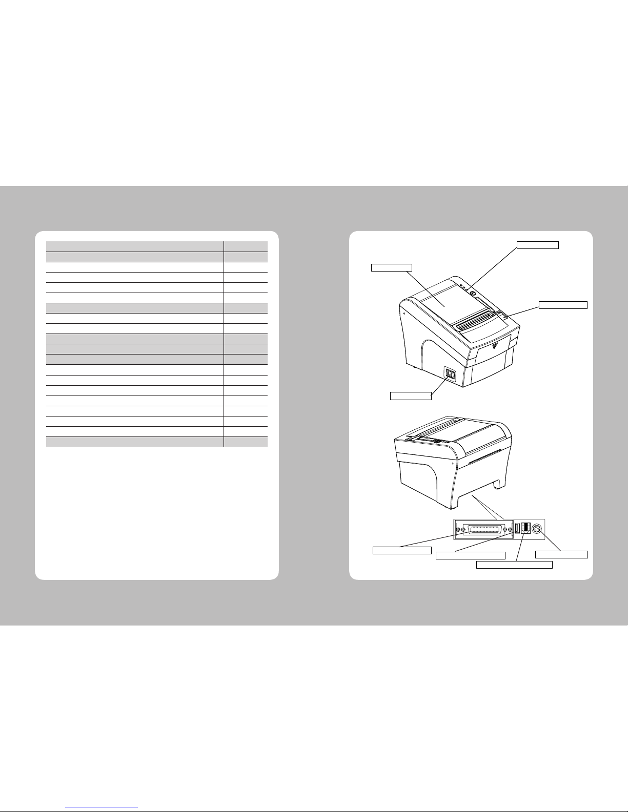
Table of Contents 1. Parts Identifications
PRINTER COVER
POWER SWITCH
COVER OPEN LEVER
CONTROL PANEL
Open this cover to
load or replace paper.
Used to turn on/off
power to the printer.
Pull down this lever to
open the printer cover.
Features LED indicators
to indicate printer status
and switches to operate
the printer.
INTERFACE CONNECTOR INTERFACE CONNECTOR(USB)
PERIPHERAL DRIVE CONNECTOR
POWER CONNECTOR

45
2-2. Connecting the Cables
You can connect up the cables required for printing to the printer.
They all connect to the connector panel on the back of the printer, which is shown below :
Before connecting any of the cables, make sure that both the printer and the computer are turned off.
2-1. Unpacking
Your printer box should include these items. If any items are damaged or missing, please contact your
dealer for assistance.
The Printer User's Manual Roll Paper
Interface Cable(optional) Adaptor(Optional)
2. Setting Up the Printer
For connection to a
host computer.
For connection to a
host computer. For connection of
the AC adapter.
Never unplug the
AC adapter while
the printer is on.
Connects to peripheral units
such as cash drawers, etc.
Do not connect this to
a telephone.
INTERFACE CONNECTOR INTERFACE CONNECTOR(USB)
PERIPHERAL DRIVE CONNECTOR
POWER CONNECTOR

67
Centronics Parallel Interface
PIN SIGNAL I/O DESCRIPTION
1 STROBE- Input Synchronize signal Data received
2~9 DATA0~7 Input/Output Data bit Transmitted 0~7
10 ACK- Output Data receiving completed.
11 BUSY Output Impossible to print of data receiving.
12 PE Output Paper empty
13 SELECT Output Printer status for ON/OFF line
14 AUTO FEED- Input Paper auto feed signal
15 GROUND - System ground
16 GROUND - System ground
17 NC -
18 LOGIC-H - +3.3V
19~30 GROUND - System ground
31 INIT- Input Initialize
32 ERROR- Output Printer error
33 GROUND - System ground
34 NC -
35 NC -
36 SELLECT IN- Input Printer select signal
Ethernet Interface
PIN SIGNAL I/O
1 Data Out + Output Data +
2 Data Out - Output Data -
3 GND Ground
4 Data IN + Input Data +
5Data IN - Input Data -
6 N.C
7 N.C
8 N.C
2-2-1. Interface Connector
<D-SUB 25 Female Serial> <Centronics Parallel>
<USB “A” Type> <Ethernet>
USB Interface
PIN SIGNAL I/O DESCRIPTION
1 +5V - +5V
2DATA- - Printer transmit data line
3 DATA+ - Printer transmit data line
4 GND - System Ground
Serial Interface
PIN SIGNAL I/O DESCRIPTION
2 TxD Output Printer transmit data line RS-232C level
3 RxD Input Printer receive data line RS-232C level
4, 20 DTR Output Printer handshake to host line RS-232C level
6 DSR Input Data Send Ready
1, 7 GND - System Ground

89
2-3. Loading the Roll Paper
Notes: Be sure to use paper rolls that meet the specifications. Do not use paper rolls that have the
paper glued to the core because the printer cannot detect the paper end correctly.
(Turn off power switch)
1. Make sure that the printer is not receiving data; Otherwise, data may be lost.
2. Open the paper roll cover by pushing down the cover open button.
3. Remove the used paper roll core if there is one inside.
4. Insert new paper roll as shown.
2-2-2. Cash Drawer Connector
The printer can operate two cash drawers with a 6 pin RJ-11 modular connector.
The driver is capable of supplying a maximum current of 1.0A / 24VDC for 510ms or less when not
printing.
PIN SIGNAL DESCRIPTION
1 Signal GND -
2 Drawer kick-out drive signal 1 Output
3 Drawer open/close signal Input
4 +24V -
5 Drawer kick-out drive signal 2 Output
6 Signal GND -
Caution : To avoid an overcurrent, the resistance of the drawer kick-out solenoid must be
24 Ω or more.

10 11
2-4. Dip Switch Setting
The printer is set up at the factory to be appropriate for almost all users. On the other hand,
offers some more settings for users with special requirements.
It has DIP switches that allow you to change communication setting, such as handshaking and parity
check, as well as print density.
Your printer has one set of DIP switches. The functions of the switches are shown in the following
tables.
♣Note : Power off. And open the cover of Dip Switch and change setting.
2-4-1. Serial Interface Specification
DIP Switch Setting (Standard)
SW FUNCTION ON OFF
2 Hexadecimal HEXDUMP NORMAL
5 Cut Mode Full Cut Partial Cut
6 Handshaking XON/XOFF DTR/DSR
8 Paper Low Mode Paper Low Detect Do not detect
Print Density
Function SW-3 SW-4
Low Power ON ON
Normal OFF ON
Normal ON OFF
Dark OFF OFF
Baud rate selection
Transmission Speed SW-9 SW-10
115200 BPS ON ON
9600 BPS OFF ON
19200 BPS ON OFF
38400BPS OFF OFF
5. Be sure to note the correct direction that the paper comes off the roll.
6. Pull out a small amount of paper, as shown. Then, close the cover.
7. Tear off the paper as shown.

12 13
♣CAUTION:
Turn off the printer while removing the DIP switch cover to prevent an electric short, which can
damage the printer.
1. Make sure the printer is turned off.
2. Take off the DIP switch cover as shown in the illustration below.
3. Set the switches using a pointed tool, such as tweezers or a small screwdriver.
4. Replace the DIP switch cover. .
The new settings take effect when you turn on the printer.
♣CAUTION:
When the paper is jammed with cutter, the top cover might be stuck. In this case, repeat power on
and off several times.
If the top cover is still stuck, please follow the steps to release the papers from jamming.
1. Make sure the printer is turned off.
2. Take out DIP switch cover as shown.
3. Turn screw with drivers to a direction until paper is released from the cutter.

14 15
3-1. Control panel
You can control the basic paper feeding operations of the printer with the button on the control panel.
The indicator lights help you to monitor the printer’s status.
Control Panel
Button
The button can be disabled by the ESC c 5 command.
Press the FEED button once to advance paper one line. You can also hold down the FEED button to
feed paper continuously.
3-2. Error indicators
This section explains the different patterns signaled by the three LED indicators located on the top
cover of the printer.
STATUS PAPER ERROR POWER REMARKS
RED RED GREEN
Power off OFF OFF OFF Normal power is not supplied to
the printer
Power on OFF OFF ON Normal power is supplied to the
printer
On line OFF OFF ON Normal error-free mode
Cover open OFF ON ON Close cover
Paper empty OFF ON ON Insert new paper roll
Paper near end ON OFF ON Paper is low
Test mode OFF OFF ON Ignored error led
3. Control panel and other functions
The self-test lets you know if your printer is operating properly. It checks the control circuits, printer
mechanisms, print quality, ROM version and DIP switch settings.
This test is independent of any other equipment or software.
Running the self test
1. Make sure the printer is turned off and the printer cover is closed properly.
2. While holding down the FEED button, turn on the printer using the switch on the front of
the printer to begin the self-test. The Self Test prints the printer settings and then prints the
following, Cuts the paper, and pauses. (Error LED On)
Self-test printing
Please press the PAPER FEED button.
3. Press the FEED button to continue printing.
The printer prints a pattern using the built-in character set.
4. The self test automatically ends and cuts the paper after printing the following.
*** Completed ***
The printer is ready to receive data as soon as it completes the self-test.
4. Self Test

16 17
This feature allows experienced users to see exactly what data is coming to the printer. This can be
useful in finding software problems.
When you turn on the hex dump function, the printer prints all commands and other data in
hexadecimal format along with a guide section to help you find specific commands.
To use the hex dump feature, follow these steps
1. After you make sure that the printer is off and Dip s/w 1-2 is ON, turn on the printer.
2. Run any software program that sends data to the printer. The printer prints “Hexadecimal Dump”
and then all the codes it receives in a two-column format. The first column contains the hexadecimal
codes and the second column gives the ASCⅡ characters that correspond to the codes.
Hexadecimal Dump
1B 21 00 1B 26 02 40 40 .!..& . @ @
1B 25 01 1B 63 34 00 1B .%.. c4 ..
41 42 43 44 45 46 47 48 ABCDEFGH
□ A period (.) is printed for each code that has no ASCⅡequivalent.
3. Turn off the printer, and make sure that Dip sw 1-2 off.
4. Turn on the printer.
5. Hexadecimal Dump 6. Specifications
Appendix A : Specifications
6-1. General Specifications
(1) Printing Method Direct line thermal printing.
(2) Print speed 160mm/sec
(3) Dot density
180 DPI (Hor / Ver) 180 / 180 (0.142mm / 0.142mm dot)
203 DPI (Hor / Ver) 203 / 180 (0.125mm / 0.142mm dot)
(4) Printing Width
180 DPI Max 72mm (512 dots)
203 DPI Max 72mm (576 dots)
(5) Number of print columns.
No. of columns
Font “A” Font “B”
180 DPI 42 56
203 DPI 48 64
(6) Roll paper Refer to chapter 2 for details on the recommended roll Paper.
Paper width : 50mm~82.5mm
Roll diameter : Max. Ø80mm
(7) Weight 3.75 lbs (1.7Kg)
Table des matières
Autres manuels DigiPos Imprimante


