DELTA BREEZ 80RLED-ADJ Manuel utilisateur

VENTILATION FAN / LED LIGHT
MODELS 80RLED-ADJ / ITG80RLED
TABLE OF CONTENTS
Package Contents
General Safety Information
Preparation and Wiring Diagrams
Assembly Instructions - New Construction
Assembly Instructions - Existing Construction
Grille Installation
Care and Maintenance
Troubleshooting
Dimensions
Product Specications
Warranty
2
3
4
5
6
8
9
10
11
11
12
READ AND SAVE THESE INSTRUCTIONS
Address: 46101 Fremont Boulevard, Fremont, CA 94538
US Toll Free Number:
1-888-979-9889 – Technical Support
1-877-685-4384 – Customer Sales Support
www.deltabreez.com
MFG Model
VFB080B4RLED1

2 3
PACKAGE CONTENTS
1
3
2
PART DESCRIPTION QTY
1Fan Body 1
2Grille 1
3Duct Connector 1

2 3
GENERAL SAFETY INFORMATION
READ AND SAVE THESE INSTRUCTIONS
GENERAL SAFETY INFORMATION
1. Make sure that the electric service supply voltage is AC
120V, 60Hz.
2. Follow all local electrical and safety codes, as well as
the National Electrical Code (NEC) and the Occupational
Safety and Health Act (OSH Act).
3. Always disconnect the power source before working on
or near the ventilating fan, motor or junction box.
4. Protect the power cord from sharp edges, oil, grease,
hot surfaces, chemicals or other objects.
5. Do not kink the power cord.
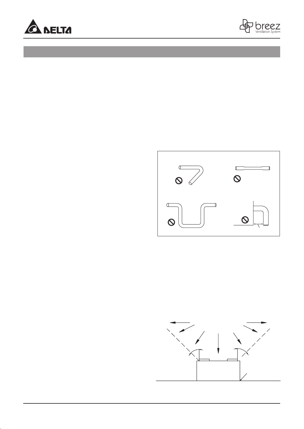
6. Do not install the unit where ducts are confugured as
shown in Fig.A.
7. Provide suction parts with proper ventilation.
8. This unit is UL Listed for use over a bathtub or shower
when installed in a GFCI protected branch circuit.
WARNING
TO REDUCE THE RISK OF FIRE, ELECTRIC
SHOCK, OR INJURY TO PERSONS, OBSERVE THE
FOLLOWING:
1. Use this unit only in the manner intended by the
manufacturer. If you have questions, contact the
manufacturer.
2. Before servicing or cleaning the unit, switch the power o
at the service panel and lock the service disconnecting
means to prevent the power from being switched on
accidentally. When the service disconnecting means
cannot be locked, securely fasten a prominent warning
device, such as a tag, to the service panel.
3. Installation work and electrical wiring must be done by
a qualied person(s) in accordance with all applicable
codes and standards, including re-rated construction.
4. Sucient air is needed for proper combustion and
exhausting of gases through the ue (chimney) of fuel
burning equipment to prevent backdrafting. Follow the
heating equipment manufacturer’s guideline and safety
standards such as those published by the National
Fire Protection Association (NFPA), and the American
Society for Heating Refrigeration and Air Conditioning
Engineers (ASHRAE) and local code authorities.
5. When cutting or drilling into the ceiling, do not damage
electrical wiring and other hidden utilities.
6. Ducted ventilating fans must always be vented to the
outdoors.
7. If this unit is to be installed over a tub or shower, it
must be marked as appropriate for the application
and be connected to a GFCI (Ground Fault Circuit
lnterrupter) – protected branch circuit.
8. Do not use this unit with any other solid-state control
device. Solid-state controls may cause harmonic
distortion, which can cause a motor humming noise.
9. NEVER place a switch where it can be reached from a
tub or shower.
10. Not to be installed in a ceiling thermally insulated to a
value greater than R40. (This is required for installation
in Canada only).
Turning angle too large
Too many elbows
Fig. A
Duct shrink
Elbow near the body
.
Body
Minimum 18 in.
CAUTION
1. For general ventilating use only. Do not use to exhaust
hazardous or explosive materials and vapors.
2. Not for use in cooking areas. (Fig.B)
3. This product must properly connect to the grounding
conductor of the supply circuit.
4. To reduce the risk of injury to persons, install the fan at
least 8.2 feet (2.5m) above the oor.
Cooking area
Do not install above or
inside this area
Cooking
Equipment
Fig. B
oor
45°
45°

4 5
Tools Required for Assembly (not included): Hammer,
Flathead Screwdriver, Wire Nuts, Nails, Duct Tape,
Phillips Head Screwdriver, Utility Knife
Helpful Tools (not included): Electric Drill, Drill Bits
WARNING: Turn o electricity at breaker box
before beginning installation.
Carefully remove unit from carton.
Check area above installation location to be sure
that wiring can run to the planned location and
that duct work can be run. Make sure the area is
sucient for proper ventilation.
Inspect duct work and wiring before proceeding
with installation.
Before installation, provide inspection and future
maintenance access at a location that will not
interfere with installation work.
You may need the help of a second person to
install this fan: one person on the attic side and
one on the room side.
Note: Installations may vary depending on how the
previous bath fan was installed. Supplies necessary
for the installation of your bath fan are not all included.
However, most are available at your local home
improvement or hardware store.
Proper insulation around the fan to minimize building
heat loss and gain. 4” circular duct is recommended
for installation. The ducting from this fan to the
outside of building has a strong eect on air ow,
noise and energy use of the fan. Use the shortest,
straightest duct routing possible for best performance,
and avoid installing the fan with smaller ducts than
recommended. Insulation around the ducts can
reduce energy loss and inhibit mold growth. Fans
installed with existing ducts may not achieve their
rated air ow.
The fan will operate most eciently when located
where the shortest possible duct run and minimum
number of elbows will be needed.
Use a roof cap or wall cap that has a built-in
damper to reduce backdrafts.
External timer/dimmer switch can be used. Please
contact Delta Breez customer service and consult
with a licensed electrician for compatibility.
PREPARATION
JUNCTION BOX SWITCH BOX
OFF
ON
HI
BLACK
POWER SWITCH
L
L
N
N
GRD
WHITE
LIGHT SWITCH
RED
WHITE
GREEN
Roof cap
(with built-in
damper)
Seal gap
around
housing Caulk termination
to duct
Fan housing
Short piece of flexible
duct helps alignment
and absorbs sound
or
Wall cap
(with built-in
damper)
Wall cap
(with built-in
damper)
2~3 ft straight run
before elbow
SWITCH BOX
ON/OFF SWITCH
(purchase separately)
POWER
SWITCH
RED BLACK
GROUND
(bare)
120 VAC
LINE IN
WHITE
WIRING
PLATE
LIGHT
SWITCH
WIRING DIAGRAM

4 5
1
3
1
1Joist or
wall stud
1
Joist or
wall stud
1
ASSEMBLY INSTRUCTIONS
NEW CONSTRUCTION
BEFORE INSTALLATION
Turn o power source. Review all safety precautions.
1. Attach the Duct Connector 3to the Fan Body 1.
2. Remove the wiring box cover from the Fan
Body 1. Remove the wiring knockout from the
wiring box cover with a athead screwdriver (not
included).
3. Place the Fan Body 1next to a ceiling joist or
wall stud. The Fan Body 1should be level and
perpendicular to the joust or stud.
4. Mount the Fan Body to the joist or stud using 2 nails
(not included) were indicated.
1
2
3
4

6 7
ASSEMBLY INSTRUCTIONS
5. Remove the fan junction box cover. Using wire
nut(not supplied), connect house wires to fan
wires as shown in the wiring diagram on page
4. 14AWG is the smallest conductor that shall
be used for branch circuit wiring. Reattach fan
junction box cover.
6. Install a circular 4 in. duct (not included) and
secure it with duct tape or clamps
(neither included).
Finish ceiling work. The ceiling hole should be
aligned with the edge of the fan housing.
EXISTING CONSTRUCTION
BEFORE INSTALLATION
Turn o power source. Review all safety precautions.
1. Remove existing fan.
2. Measure the opening to ensure it is large enough
to accommodate the new Fan Body
(7 1/2in. x 7 1/4in.).
Note: 7 1/4 inch side of opening should be ush
with the joist.
wire nut
(not included)
Product
wires
House
wires
Ceiling
4 in. Duct
Duct tape
or clamp
5
6
1
2

6 7
ASSEMBLY INSTRUCTIONS
3. If this fan is not replacing an old fan, be sure to cut
a 7 1/2in. x 7 1/4in. opening for the Fan Body 1.
Make sure the 7 1/4 inch side of opening is ush
with the joist for installation from below.
4. Attach the Duct Connector 3to the Fan body.
Remove the wiring box cover from the Fan
Body 1. Remove the wiring knockout from the
wiring box cover with a athead screwdriver (not
included). Remove the three screws that hold
the fan motor assembly in place. Remove the fan
motor assembly from the Fan Body 1. Unplug
fan connector.
5. Remove the fan junction box cover. Using wire
nut(not supplied), connect house wires to fan wires
as shown in the wiring diagram on page 4. 14AWG
is the smallest conductor that shall be used for
branch circuit wiring. Reattach fan junction box
cover. Reattach fan junction box cover.
6. Install a circular 4 in. duct (not included) and
secure it with duct tape or clamps (neither
included).
Mount the Fan Body 1to the joist or stud using
nails (not included) were indicated.
7. Plug the fan connector and fan assembly back
into the Fan Body 1. Reattach the fan assembly
using the three screws removed in step 4.
wire nut
(not included)
Product
wires
House
wires
5
9.4"
9.4"
7 1/2 in.
7 1/4 in.
3
Tape
❶
Joist or wall stud
Nail
4 inch duct
6
1
3
4
7

8 9
GRILLE INSTALLATION
For the LED light connection, plug in the connector
from the grille into the fan housing as shown.
Pinch the mounting springs on the Grille 2, and insert
them into the narrow rectangular slots inside the fan.
Push the Grille 2up toward the ceiling.
Using the switch on the back of grille, choose the color
temperature you want for your LED.
You can choose from 2700K warm white, 4000K cool
white, and 5000K daylight white.
Turn on electricity at the breaker box after nishing
installation.
CCT Switch
2

8 9
See safety information before proceeding. Routine maintenance should be done at least once a year.
• Never use solvents, thinner or harsh chemicals when cleaning the fan.
• Do not allow water to enter the motor.
• Do not immerse metal parts in water.
• Do not immerse resin parts in water over 140º Fahrenheit.
Turn o power source. Review all safety precautions.
1. To remove grille 2, squeeze springs and pull down.
2. Clean the grille 2with a dry cloth.
3. Remove dust and dirt from the fan body 1with
a vacuum cleaner.
4. Dampen cloth with dust detergent and wipe the fan body
1. Then wipe dry with a clean cloth.
5. Replace grille 2back onto fan body 1,
refer to page.8 Grille Installation.
6. Turn on power source to operate fan again.
CARE AND MAINTENANCE
2
2
2
1Vacuum
cleaner
1
1
2
4
3
5

10 11
TROUBLESHOOTING
PROBLEM POSSIBLE CAUSE CORRECTIVE ACTION
The fan is not turning on 1. Power o
2. Faulty switch
3. Faulty wire connection
1. Make sure power supply is on.
2. Test or replace switch.
3. Check wire in switch box.
The fan seems louder
than it should
1. CFM too great
2. Damper not working
properly or damaged
3. Bend in duct too close
to fan discharge
4. Fan discharge duct
5. Fan body not securely
attached
1. Be sure the CFM rating on the fan matches the
size of your room.
2. Check damper to ensure it is opening and
closing properly. If the damper has become
damaged, please call Customer Service.
3. Be sure you do not have any sharp bends in
duct closer than 18 in. to the fan discharge.
4. Use recommended size ducting to reduce fan
noise.
5. Be sure the fan is securely attached to your
ceiling joists.
The fan is not clearing
the room
1. Insucient intake
airfow within room
2. Insucient CFM
1. Be sure a door or window is slightly ajar or
opened to allow airow. The fan is not able to
draw air out of the room without enough airow
to draw in from.
2. Be sure the CFM rating on the fan matches the
requirements for your room size.
The light is not turning
ON
1. Power o
2. Faulty switch
3. Faulty wire connection
1. Make sure power supply is on.
2. Test or replace switch.
3. Check wire in switch box.
Ce manuel convient aux modèles suivants
1
Table des matières
Autres manuels DELTA BREEZ Ventilateur

DELTA BREEZ
DELTA BREEZ SIG80-110ELED Manuel utilisateur

DELTA BREEZ
DELTA BREEZ PRO Series Manuel utilisateur

DELTA BREEZ
DELTA BREEZ RAD80L Manuel utilisateur

DELTA BREEZ
DELTA BREEZ ITG50LED Manuel utilisateur

DELTA BREEZ
DELTA BREEZ VCA605LED-HEBK Manuel utilisateur

DELTA BREEZ
DELTA BREEZ AMR1200 Manuel utilisateur

DELTA BREEZ
DELTA BREEZ SIG80 Manuel utilisateur

DELTA BREEZ
DELTA BREEZ 80RLED-ADJ-BN Manuel utilisateur

DELTA BREEZ
DELTA BREEZ 80LED-REC Manuel utilisateur