
Datcon DT1102 M (PS) Manuel utilisateur
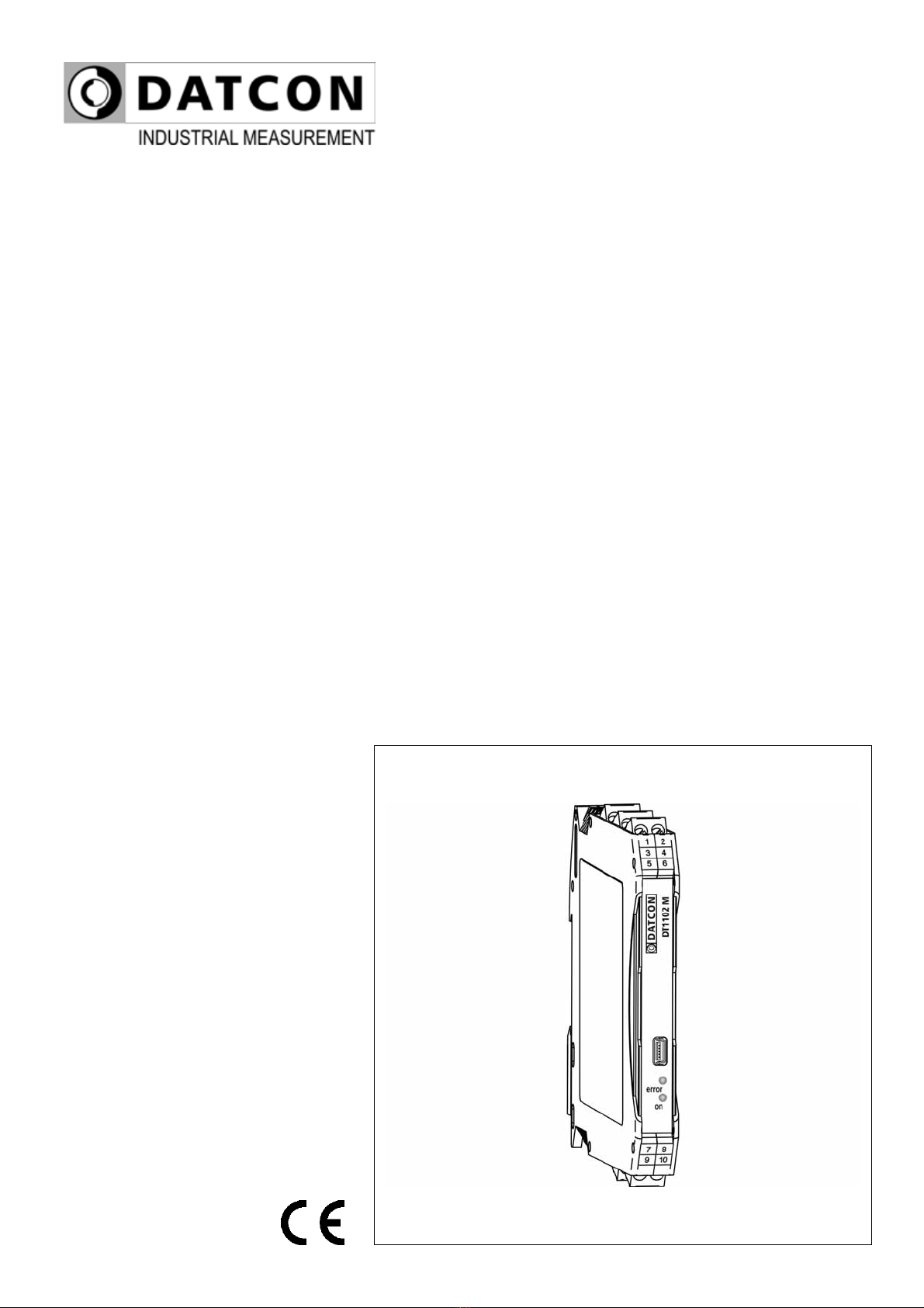
DT1102 M (PS)
MODBUS Output Galvanic Isolator
Operating Instructions

DT1102 M
2 20230127-V0
Contents
1. About this document..............................................................4
1.1. Function...............................................................................................4
1.2. Target group........................................................................................4
1.3. Symbolism used ..................................................................................4
2. For your safety........................................................................5
2.1. Authorized personnel...........................................................................5
2.2. Appropriate use ...................................................................................5
2.3. Warning about misuse......................................................................... 5
2.4. General safety instructions ..................................................................5
2.5. CE conformity......................................................................................5
2.6. Environmental instructions................................................................... 5
3. Product description................................................................6
3.1. Delivery configuration ..........................................................................6
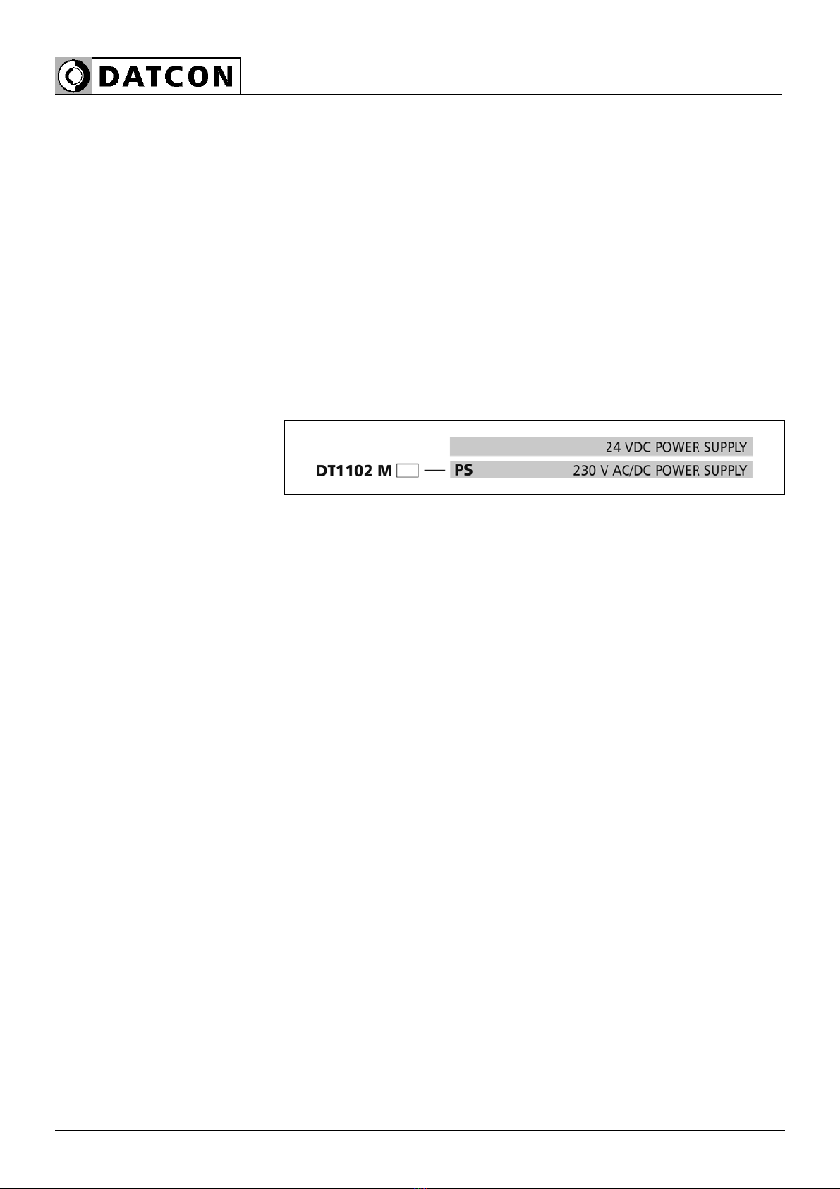
3.2. Type designation ................................................................................. 6
3.3. Operating principle ..............................................................................7
3.4. Adjustment ..........................................................................................8
3.5. Indicators, USB connector................................................................... 9
3.6. Storage and transport.......................................................................... 9
4. Mounting ...............................................................................10
4.1. General instructions........................................................................... 10
4.2. Main dimensions of the instrument .................................................... 10
4.3. Mounting procedure........................................................................... 11
5. Connecting............................................................................12
5.1. Preparing the connection................................................................... 12
5.2. Connecting the DC current signal source .......................................... 13
5.3. Connecting a -2.5 - +2.5 VDC voltage signal source ......................... 14
5.4. Connecting a -125 - +125 VDC voltage signal source ....................... 15
5.5. Connecting the signal processing unit and the power supply............. 16
5.6. Put the instrument under supply voltage............................................ 17
5.7. Connecting to PC via USB cable ....................................................... 18
6. The first start-up, indicators ................................................19
6.1. The first start-up ................................................................................ 19
6.2. Indicator LED-s.................................................................................. 20

DT1102 M
20230127-V0 3
7. Setting-up..............................................................................21
7.1. First steps.......................................................................................... 21
7.2. Analogue input type setting ............................................................... 23
7.3. Analogue input range setting ............................................................. 24
7.4. MODBUS communication parameters setting ................................... 25
7.5. MODBUS registers ............................................................................ 26
7.6. Resetting default setting .................................................................... 27
7.7. Display measured data...................................................................... 28
7.8. Display system information................................................................ 28
7.9. Display errors .................................................................................... 29
8. Fault rectification..................................................................30
8.1. Fault finding....................................................................................... 30
8.2. Repairing ........................................................................................... 30
9. Dismounting..........................................................................31
9.1. Dismounting procedure...................................................................... 31
9.2. Disposal............................................................................................. 31
10. Appendix.............................................................................32
10.1. Technical specification..................................................................... 32
10.2. Application example ........................................................................ 35
DT1102 M
4 20230127-V0
1. About this document
1.1. Function
This operating instructions manual has all the information you
need for quick set-up and safe operation of DT1102 M (PS).
Please read this manual before you start setup.
1.2. Target group
This operating instructions manual is directed to trained personnel.
The contents of this manual should be made available to these
personnel and put into practice by them.
1.3. Symbolism used
Information, tip, note
This symbol indicates helpful additional information.
Caution, warning, danger
This symbol informs you of a dangerous situation that could occur.
Ignoring this cautionary note can impair the person and/or the
instrument or it’s environ.
•List
The dot set in front indicates a list with no implied sequence.
→Action
This arrow indicates a single action.
1 Sequence
Numbers set in front indicate successive steps in a procedure.

DT1102 M
20230127-V0 5
2. For your safety
2.1. Authorized personnel
A
ll operations described in this operating instructions manual must
be carried out only by trained and authorized specialist personnel.
For safety and warranty reasons, any internal work on the
instruments must be carried out only by DATCON personnel.
2.2. Appropriate use
The DT1102 M (PS) is a MODBUS Output Galvanic Isolator for
industrial use. Detailed information on the application range is
available in chapter 3. Product description.
2.3. Warning about misuse
Inappropriate or incorrect use of the instrument can give rise to
application-specific hazards, or damage to system components
through incorrect installing or adjustment.
2.4. General safety instructions
Using the DT1102 M (PS) MODBUS Output Galvanic Isolator
requiring the strict observance of standard regulations and
guidelines.
The user must take note of the safety instructions in this operating
instructions manual, the country-specific installation standards as
well as all prevailing safety regulations and accident prevention
rules.
2.5. CE conformity
The DT1102 M (PS) is in conformity with the provisions of the
following standards:
EN 61326-1:2013 (EMC)
EN 61010-1:2011 (Safety)
2.6. Environmental instructions
Protection of the environment is one of our most important duties.
Please take note of the instructions written in the following
chapters:
•Chapter 3.6. Storage and transport
•Chapter 9.2. Disposal
DT1102 M
6 20230127-V0
3. Product description
3.1. Delivery configuration
Delivered items The scope of delivery encompasses:
•DT1102 M (PS)
•documentation:
this operating instructions manual
certification
warranty
mini USB (5 pin) - USB A cable
setup software on CD
3.2. Type designation

DT1102 M
20230127-V0 7
3.3. Operating principle
Area of application The DT1102 M (PS) MODBUS Output Galvanic Isolator provide
signal transmission and conversion between DC current or DC
voltage signal source and signal processing units.
The instruments feature complete 3-way isolation: the input, the
output and the power supply are isolated from each other.
The instruments has three bipolar symmetrical inputs:
1. -25 mA - +25 mA DC current,*
2. -2.5 - +2.5 V DC voltage,*
3. -125 - +125 V DC voltage.*
The instruments has one output:
RS485 MODBUS RTU/ASCII slave
* You must use one input at a time.
The PC configurator software is accessory or free downloadable
from homepage: www.datcon.hu
The input type and range and the MODBUS communication
parameters are configurable (current or voltage). See chapter
10.1. Technical specification.
The configuration parameters can be download from
the PC to the DT1102 M via USB port.
The front panel LED indicators provide information about the
operating status of the device.
Principle of operation
The input current flows through the measuring resistor or the input
voltage is divided by the attenuator. This voltage is measured by a
24-bit A/D converter. The digital output signal of the A/D converter
is processed by a microcontroller. The measured values are
reading from instruments via galvanically isolated RS485 interface
using MODBUS RUT/ASCII protocol.
The instrument’s power supply produces two galvanically isolated
supply voltages, one of for input side and one of for output side.

DT1102 M
8 20230127-V0
Connecting the instrument to the PC through the USB interface
the instrument’s communication circuitry come into active state
and it is ready for communication with the configuration software.
The USB port is galvanic isolated therefore the USB cable can
plugged into a grounded PC too.
Power supply The DT1102 M (PS) is available two different power supply:
DT1102 M: 24 VDC ±10%
<1.2 W / 1.8 VA
DT1102 M PS: 230 V AC/DC ±10%
<1.9 VA / 1.3 W
3.4. Adjustment
After connecting the DT1102 M is ready to work with the factory
default parameters are written in chapter 6.1. The first start-up.
For working with the default parameters there is no need any
adjustment. The detailed description of the setup can be found in
chapter 7. Setting-up.
DT1102 M
20230127-V0 9
3.5. Indicators, USB connector
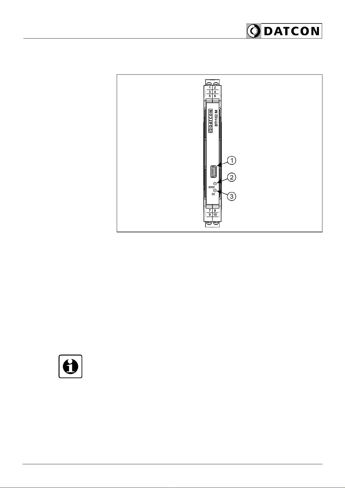
The following figure shows the indicators and USB connector on
the DT1102 M front panel.
1. USB-B mini, 5 pole connector for connecting to the PC at
configuration.
2. The „error” red indicator blinking light indicates different error
states.
3. The „on” green indicator continuous light indicates that the
instrument is working.
3.6. Storage and transport
This instrument should be stored and transport in places whose
climatic conditions are in accordance with chapter
10.1. Technical specification, as described under the title:
Ambient conditions.
The packaging of DT1102 M consist of environment-friendly,
recyclable cardboard is used to protect the instrument against the
impacts of normal stresses occurring during transportation. The
corrugated cardboard box is made from environment-friendly,
recyclable paper. The inner protective material is polyfoam and
nylon, which should be disposed of via specialized recycling
companies.
DT1102 M
10 20230127-V0
4. Mounting
4.1. General instructions
The instrument should be installed in a cabinet with sufficient IP
protection, where the operating conditions are in accordance with
chapter 10.1. Technical specification, as described under the
title: Ambient conditions.
Mounting position
The instruments are designed in a housing for mounting on TS-35
rail.
The instruments should be mounted in vertical position (horizontal
rail position).
Horizontal mounting may cause overheating and damage of the
instrument.
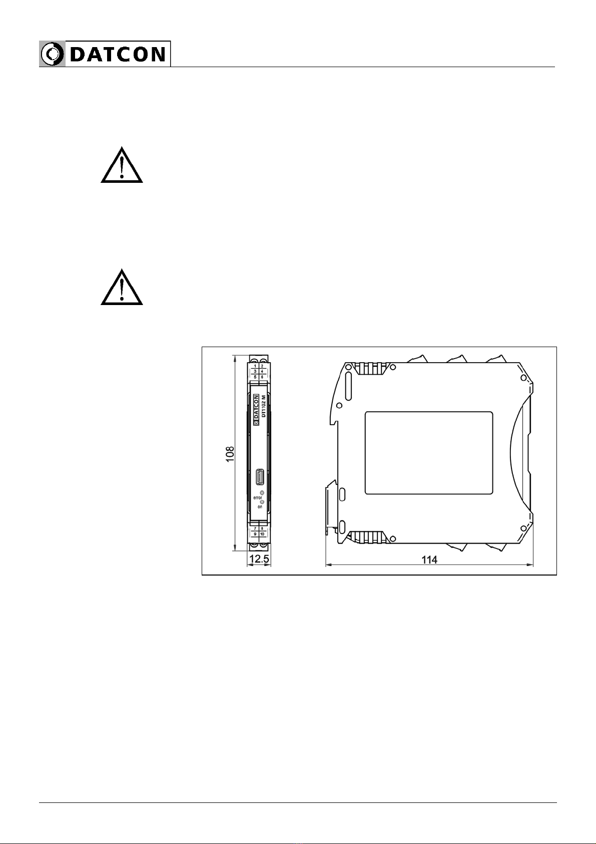
4.2. Main dimensions of the instrument
The following figure shows the main dimensions of the instrument.
Table des matières
Autres manuels Datcon Équipement industriel


