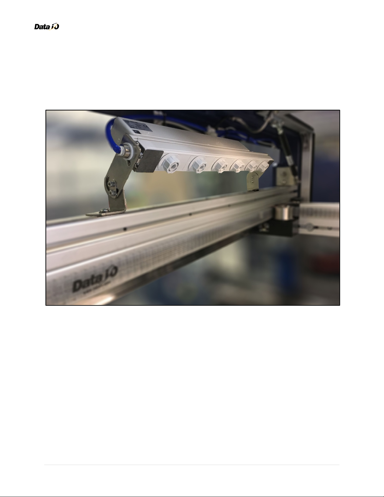
Data I/O PSV7000 Manuel utilisateur

© 2018 | Data I/O Corporation
Part Number: 123-4567-001A
Data I/O
PSV7000 Ionizer Kit

PSV7000 Ionizer Kit
Contents
Chapter 1: Introduction........................................................................................................................ 1
Safety Warnings ........................................................................................................................................ 2
Package Contents...................................................................................................................................... 3
Specifications ............................................................................................................................................ 3
Requirements............................................................................................................................................ 4
Chapter 2: Mounting the Hardware ..................................................................................................... 5
Mount the Ionizer ..................................................................................................................................... 5
Connect the Air Tubing ............................................................................................................................. 6
Mount the Air Pressure Regulator .......................................................................................................... 11
Chapter 3: Testing the Ionizer ............................................................................................................ 15
Verify Air and Power ............................................................................................................................... 15
Verify ESD Elimination............................................................................................................................. 16
Chapter 4: Optimizing and Maintenance ............................................................................................ 17
Check the Ionizer Electrode(s) ................................................................................................................ 17
Maintenance Schedule............................................................................................................................ 18
Obtain Parts and Supplies ....................................................................................................................... 18

PSV7000 Ionizer Kit
1 | Page
Chapter 1: Introduction
The PSV7000 Ionizer Kit from Data I/O is a hardware ionizer designed to neutralize static electricity
within the system. The ionizer is implemented in compliance with the requirements of International
Standards IEC 61340-5-1 and IEC 61340-4-7. This kit includes all mounting hardware, system ionizer(s),
air pressure regulator, and Power and Air cables.
The ionizer operates as follows under normal operation:
•the ionizer generates ions of different polarity alternately to de-ionize the air and
optimize ion balance to within ±10V in energy-saving static electricity elimination mode
•small holes along the ionizer serve as emitter points for the neutralizing ions
•these holes improve the distribution and coverage of ions that eliminate static electricity
(factory settings eliminate static electricity within 3.2 seconds at 1000 mm distance)
This document provides instructions for mounting the ionizer hardware, connecting and routing the
Power and Air cables, and testing the ionizer for static electricity reduction/elimination.
Note: For Dual Ionizer configurations, this document notes any variations
(between single and dual ionizers) with an indented Note paragraph.

PSV7000 Ionizer Kit
2 | Page
Safety Warnings
To avoid personal injury and equipment damage, it is required that you comply with all safety rules and
regulations. Although the PSV7000 Ionizer Kit involves no moving parts, the ionizer carries an electrical
charge when installed.
The system can be dangerous if safety precautions are ignored. Do not operate the system unless you
have been thoroughly trained. Do not disable or attempt to defeat any of the safety features of the
system. Failure to adhere to safety warnings, operate the equipment properly under normal use, and
apply safety practices constitutes a violation of your warranty agreement.
WARNING: Electric Shock Hazard!
Injury or death may result from contact to parts inside the equipment. Do not remove covers.
There are no user-serviceable parts. Tampering with the ionizer and/or any of its components
may result in damage, personal injury, electrical shock, or fire.
Never connect Power to any component that appears compromised, damaged, or tampered
with (ex. covers removed, wires hanging loose, etc.). Prior to connecting Power of any kind,
confirm the voltage requirements of your unit.
Keep hands and fingers away from ionizer emitter points to avoid electrical shock.
Ozone condensation can increase in enclosed spaces. Use ionizers in a well-ventilated facility to reduce
ozone exposure. For information about ozone condensation, refer to the documentation from the
ionizer manufacturer: http://content2.smcetech.com/pdf/IZN10.pdf.
Data I/O is not responsible for any defects or failures in the equipment caused by user negligence,
including but not limited to abuse, accident, improper maintenance, inattention, or unauthorized repair,
alteration, or installation.

PSV7000 Ionizer Kit
3 | Page
Package Contents
A. Ionizer (with mounting brackets)
B. Air hose/tubing (3 meters)
C. Air pressure regulator
D. Electrical wiring
Specifications
Length: ……………….....
25.329 cm / 9.972 in.
Width: …………………...
5.890 cm / 2.319 in.
Height (w/ platform):
11.227 cm / 4.420 in.
Total Height: ………….
(w/ extension arm)
12.700 cm / 5.000 in.

PSV7000 Ionizer Kit
4 | Page
Requirements
This page lists the tools and items required to install the PSV7000 Ionizer Kit.
Tools
•Power drill with 4.5 mm drill bit
•Metric hex key set
•Screwdriver set
•Adjustable utility wrench and/or pliers
•Cutter (for snipping wire/zip ties and air tubing)
•Handheld electrostatic/ESD meter
Additional Guidelines and Considerations
Consider the following guidance when working with the PSV7000 Ionizer Kit:
•The PSV7000 system is tested and certified to meet ANSI/NCSL Z-540-1 and national standards for
Ground Bond/PE resistance compliance (to meet electrical safety standards, the ground points of
the system are certified to be well connected—measured to 100mΩat 20.0A for 1.0 sec)
•The PSV7000 system is tested and certified to meet ANSI/NCSL Z-540-1 and national standards for
high voltage/potential insulation (to meet electrical safety standards, the electrical components of
the system are sufficiently isolated—measured to 17.00mA or under with 1.24KVAC for 1.0 sec)
•The majority of PSV7000 exposed surfaces are metallic, conductive, and bonded to earth ground;
the following surfaces are tested and certified to meet ANSI/NCSL Z-540-1 and national standards
for digital surface resistance compliance:
•Upper doors (front and rear)
•Interior workspace (front and rear)
•Pick-and-Place (PnP) probes with tensioner
•Tray feeder
•Tape-In feeder
•Tape-Out module
•PnP probes use conductive rubber nozzles/tips
•Static-dissipative Plexiglas® (grounded) is used for all clear-paneled access doors and windows
•Minimal use of electrically insulated materials are used within the PSV7000 system, except for:
•Adapter boards and sockets
•Air tubing/hoses/lines
•PnP probe vacuum chamber
The PSV7000 Ionizer Kit helps to address potential ESD within the interior workspace of the PSV7000,
including but not limited to the insulated materials above.

PSV7000 Ionizer Kit
5 | Page
Chapter 2: Mounting the Hardware
Complete the following steps to mount the hardware for the PSV7000 Ionizer Kit. This process largely
involves mounting the ionizer and routing its cables (air/electricity).
Mount the Ionizer
1. Position the ionizer above the left-side gantry (when facing the front of PSV7000), then use a 3 mm
hex key to secure it to the chassis with 2 screws (M8x1.25x20mm)—one at each end of ionizer.
Secure ionizer bracket to gantry.
2. Confirm that the ionizer is mounted securely to the gantry and nothing is loose.
Confirm ionizer is mounted securely.

PSV7000 Ionizer Kit
6 | Page
Connect the Air Tubing
1. Stick 4 adhesive cable tie mounts vertically to the upper beam of the system chassis.
Stick cable tie mounts to upper beam.
2. Cut the included air tubing into 3 pieces: 240 cm, 30 cm, and 30 cm.
3. Take a 30-cm length and insert it into one end/side of the ionizer.
Insert short length (30 cm) of air tubing into ionizer.
4. Repeat the previous step to insert the other 30-cm length of air tubing into the other end of ionizer.
(both of the short lengths—30 cm—of air tubing are now used)

PSV7000 Ionizer Kit
7 | Page
5. Connect the 2 loose ends of the air tubing (one from each end/side of the ionizer) with a Y-fitting.
Connect air tubing with Y-fitting/adapter.
6. Now take the remaining 240-cm length of air tubing and insert one end into the Y-fitting. (the other
end ultimately connects to the air pressure regulator, which connects to main/incoming air)
Insert long length (240 cm) of air tubing into Y-fitting.
Ionizer (Side/End 1)
Ionizer (Side/End 2)
Air Pressure
Regulator

PSV7000 Ionizer Kit
8 | Page
7. Connect the Power adapter to the back of the ionizer.
Plug-in the Power adapter.
8. Route the Power and Air cables along the top of the blue chassis and towards the rear of the system,
and then secure using 4 zip ties (looped through each adhesive cable mount from Step 1).
Route and secure cables toward rear.
Autres manuels pour PSV7000
1
Table des matières
Autres manuels Data I/O Système de contrôle


