Danfoss 176F4057 Manuel utilisateur

1 Overview
1.1 Description
The in-back/out-back cooling kit fits FA11 and FA12 frequency converters mounted in Rittal TS8 cabinets with widths of 600 mm (24
in) or 800 mm (32 in). When the kit is installed, air flows into the lower back duct and out through the upper back duct of the fre-
quency converter. See Illustration 1.
4
2
5
e30bf963.10
1
3
6
Illustration 1: Direction of Airflow with Kit Installed
1
Top cover
2
Cabinet
3
Pedestal
4
Cooling back channel
5
Air flow direction
6
Bottom cover
1.2 Kit Numbers
Use these instructions with the following kits.
Table 1: In-back/Out-back Cooling Kits
Number
Kit description
176F4057
In-back/out-back cooling kit for FA11 frequency converter
176F4058
In-back/out-back cooling kit for FA12 frequency converter
AN361428862578en-000101 / 136R0249 | 1Danfoss A/S © 2022.03
Installation Guide
In-back/Out-back Cooling Kit for FA11-FA12
iC7 Series Frequency Converters

1.3 Items Supplied
The following parts are contained in the kit.
Table 2: Items Supplied in In-back/Out-back Cooling Kits
Item
Quantity
Top cover
1
Top gasket
1
Bottom cover
1
Bottom gasket
1
Back duct
2
6-hole gasket
4
8-hole gasket
4
Clip-on nut
16
M5x14 screw
8–10
M5x18 screw
16
M6x12 screw
12
AN361428862578en-000101 / 136R02492 | Danfoss A/S © 2022.03
Overview
In-back/Out-back Cooling Kit for FA11-FA12
Installation Guide

-
-
-
-
-
-
-
-
-
-
-
-
-
-
2 Installation
2.1 Safety Information
NOTICE
QUALIFIED PERSONNEL
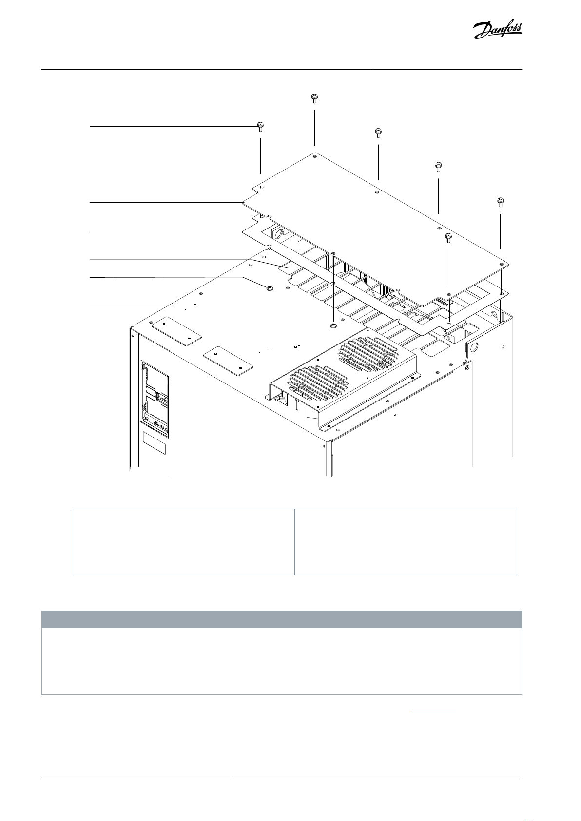
Only qualified, Danfoss authorized personnel are allowed to install the parts described in these installation instructions.
Disassembly and reassembly of the frequency converter must be done in accordance with the service guide.
Use the standard fastener torque values from the service guide, unless the torque value is specified in these instructions.
WARNING
DISCHARGE TIME (40 MINUTES)
The frequency converter contains DC-link capacitors, which can remain charged even when the frequency converter is not pow-
ered. High voltage can be present even when the warning LED indicator lights are off. Failure to wait 40 minutes after power has
been removed before performing service or repair work can result in death or serious injury.
Stop the motor.
Disconnect AC mains and remote DC-link power supplies, including battery back-ups, UPS, and DC-link connections to other
frequency converters.
Disconnect or lock the motor.
Disconnect any brake option.
Disconnect any DC connector option.
Wait 40 minutes for the DC-link capacitors to discharge fully.
Before performing any service or repair work, measure the voltage level to verify that the capacitors are fully discharged.
WARNING
ELECTRICAL SHOCK HAZARD
The frequency converter contains dangerous voltages when connected to mains voltage. Improper installation, and installing or
servicing with power connected, can cause death, serious injury, or equipment failure.
Only use qualified electricians for the installation.
Disconnect the frequency converter from all power sources before installation or service.
Treat the frequency converter as live whenever the mains voltage is connected.
Follow the guidelines in these instructions and local electrical safety codes.
NOTICE
ELECTROSTATIC DISCHARGE
Electrostatic discharge can damage components.
Ensure electrostatic discharge before touching internal frequency converter components, for example by touching a groun-
ded, conductive surface or by wearing a grounded armband.
AN361428862578en-000101 / 136R0249 | 3Danfoss A/S © 2022.03
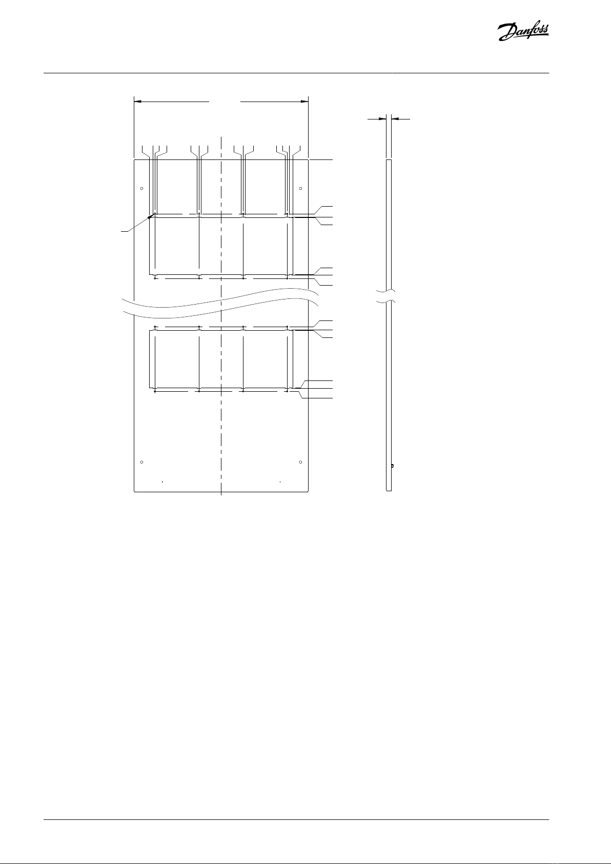
Installation
In-back/Out-back Cooling Kit for FA11-FA12
Installation Guide

-
2.2 Installation Overview
NOTICE
APPLYING GASKETS
This kit contains self-adhesive gaskets to ensure a proper seal between metal parts.
Before affixing a gasket, check that the part matches the gasket and that no holes are covered.
2
1
3
4
5
6
7
8
9
10
11
12
e30bg242.10
Illustration 2: Overview of In-back/Out-back Cooling Kit
AN361428862578en-000101 / 136R02494 | Danfoss A/S © 2022.03
Installation
In-back/Out-back Cooling Kit for FA11-FA12
Installation Guide

1.
2.
3.
4.
1
Cabinet
2
Bottom gasket
3
Bottom cover
4
M5x14 screw
5
Top cover
6
Top gasket
7
Clip-on nut
8
Back duct
9
M5x18 screw
10
6-hole gasket
11
8-hole gasket
12
M6x12 screw
2.3 Creating Vent Openings in the Mounting Plate
To create upper and lower vent openings in the mounting plate, use the following steps. Use the dimensions in Illustration 3 for 600
mm (24 in) cabinets, and Illustration 4 for 800 mm (32 in) cabinets.
Procedure
Drill 6 mounting holes in the back of the frequency converter using the dimensions in the template.
Insert 6 M10 pem self-clinching nuts (not supplied) in the mounting holes.
Cut out the upper and lower vent openings in the mounting plate using the dimensions in the template.
The openings must match the frequency converter vent openings.
Drill 6 screw holes around each vent opening using the dimensions in the template.
The holes must match the holes in the frequency converter and the inner flange of the back ducts.
AN361428862578en-000101 / 136R0249 | 5Danfoss A/S © 2022.03
Installation
In-back/Out-back Cooling Kit for FA11-FA12
Installation Guide

499 (19.7)
2X 246 (9.7)
230 (9.1)
206 (8.1)
2X 201 (7.9)
6X S-M10-2Z1
0.0
2X 201 (7.9)
206 (8.1)
230 (9.1)
2X 246 (9.7)
23 (0.9)
0.0
100 (3.9)
137 (5.3)
158 (6.2)
169 (6.7)
314 (12.3)
326 (12.8)
347 (13.7)
1645 (64.7)
215 (8.5)
0.0
7 (0.3)
3 (0.1)
215 (8.5)
1335 (52.6)
1357 (53.4)
1368 (53.9)
1513 (59.6)
1524 (60.0)
1545 (60.8)
2X 230 (9.1)
2X 230 (9.1)
e30bg240.10
Illustration 3: Vent Dimensions for Mounting Plate in 600 mm (24 in) Cabinet
AN361428862578en-000101 / 136R02496 | Danfoss A/S © 2022.03
Installation
In-back/Out-back Cooling Kit for FA11-FA12
Installation Guide

1.
2.
699 (27.5)
2X 246 (9.7)
230 (9.1)
254 (10.0) E4h
2X 201 (7.9)
6X S-M10-2Z1
0.0
2X 201 (7.9)
230 (9.1)
2X 246 (9.7)
23 (0.9)
0.0
100 (3.9)
137 (5.3)
158 (6.2)
169 (6.7)
314 (12.3)
326 (12.8)
347 (13.7)
1645 (64.7)
0.0
7 (0.3)
3 (0.1)
263 (10.4) E4h
1335 (52.6)
1357 (53.4)
1368 (53.9)
1513 (59.6)
1524 (60.0)
1545 (60.8)
2X 230 (9.1)
2X 230 (9.1)
e30bg244.10
206 (8.1) E3h
206 (8.1) E3h
254 (10.0) E4h
215 (8.5) E3h
263 (10.4) E4h
215 (8.5) E3h
Illustration 4: Vent Dimensions for Mounting Plate in 800 mm (32 in) Cabinet
2.4 Creating Vent Openings in the Backplate
To create upper and lower vent openings in the cabinet backplate, use the following steps. Use the dimensions in Illustration 5 for
600 mm (24 in) cabinets, and Illustration 6 for 800 mm (32 in) cabinets.
Procedure
Cut out the vent openings in the cabinet backplate using the dimensions in the template.
The openings must match the frequency converter and mounting plate vent openings.
Drill 8 screw holes (6 mm) around each vent opening using the dimensions in the template.
The holes must match the holes in the frequency converter and in the outer flange of the back duct.
AN361428862578en-000101 / 136R0249 | 7Danfoss A/S © 2022.03
Installation
In-back/Out-back Cooling Kit for FA11-FA12
Installation Guide

185 (7.3)
4X 196 (7.7)
198 (7.8)
0.0
392 (15.4)
4X 394 (15.5)
405 (15.9)
18 (0.7)
1383 (54.4)
1394 (54.9)
1396 (55.0)
1590 (62.6)
1592 (62.7)
1603 (63.1)
16X Ø 6 (0.2)
244 (9.6)
2X 232 (9.1)
225 (8.9)
2X 218 (8.6)
2X 82 (3.2)
75 (3.0)
2X 68 (2.7)
244 (9.6)
2X 218 (8.6)
225 (8.9)
2X 232 (9.1)
2X 68 (2.7)
75 (3.0)
2X 82 (3.2)
0.0
592 (23.3)
e30bg241.10
Illustration 5: Vent Dimensions for Backplate in 600 mm (24 in) Cabinet
AN361428862578en-000101 / 136R02498 | Danfoss A/S © 2022.03
Installation
In-back/Out-back Cooling Kit for FA11-FA12
Installation Guide

1.
2.
3.
4.
5.
6.
185 (7.3)
4X 196 (7.7)
198 (7.8)
0.0
18 (0.7)
392 (15.4)
4X 394 (15.5)
405 (15.9)
1383 (54.4)
1394 (54.9)
1396 (55.0)
1590 (62.6)
1592 (62.7)
1603 (63.1)
16X Ø 6 (0.2)
244 (9.6)
2X 232 (9.1)
225 (8.9)
2X 218 (8.6)
2X 82 (3.2)
75 (3.0)
2X 68 (2.7)
244 (9.6)
2X 218 (8.6)
225 (8.9)
2X 232 (9.1)
2X 68 (2.7)
75 (3.0)
2X 82 (3.2)
0.0
792 (31.2)
e30bg245.10
Illustration 6: Vent Dimensions for Backplate in 800 mm (32 in) Cabinet
2.5 Installing the Top Cover
To install the top cover, use the following steps. See Illustration 7.
Procedure
Remove paper backing from the top gasket to expose the adhesive.
Adhere the top gasket to the underside of the top cover.
Remove the M5x14 screws (T25) surrounding the sides and back of the vent in the top of the frequency converter.
Retain the screws. FA11 converters have 6 screws; FA12 converters have 7 screws.
Loosen 3 M5x12 screws (T25) at the front of the vent in the top surface of the frequency converter.
Slide the edge of the top cover plate under the 3 loosened screws, positioning the plate over the vent in the top of the
frequency converter.
Secure the top cover plate with the M5x14 screws (T25) removed previously in step 3.
Torque all screws to 2.3 Nm (20 in-lb).
AN361428862578en-000101 / 136R0249 | 9Danfoss A/S © 2022.03
Installation
In-back/Out-back Cooling Kit for FA11-FA12
Installation Guide

1.
2.
3.
-
-
1
2
3
e30bg162.10
6
4
5
Illustration 7: Installation of the Top Cover
1
M5x14 screw
2
Top cover
3
Top gasket
4
Top vent
5
M5x12 screws (loosened, not removed)
6
Top of frequency converter
2.6 Installing the Bottom Cover
NOTICE
DRAIN OPENING
The bottom cover features a drain opening in the middle of the plate.
To drain moisture in wet or humid environments, attach nylon tubing with interior diameter of 8 mm (0.3 in).
To seal the drain in dry environments, fasten a screw in the drain hole.
To install the bottom cover at the lower end of the cooling back channel, use the following steps. See Illustration 8.
Procedure
Remove the paper backing from the bottom gasket.
Adhere the gasket to the upper side of the bottom cover.
Position the bottom cover and gasket over the opening at the lower end of the cooling channel.
AN361428862578en-000101 / 136R024910 | Danfoss A/S © 2022.03
Installation
In-back/Out-back Cooling Kit for FA11-FA12
Installation Guide
Ce manuel convient aux modèles suivants
1
Table des matières
Autres manuels Danfoss Congélateur


