Dahua Technology DHI-ASC3202B Manuel utilisateur

Access Controller
Quick Start Guide
ZHEJIANG DAHUA VISION TECHNOLOGY CO., LTD. V1.0.1

Quick Start Guide
I
Foreword
General
This manual introduces the installation and operations of the Access Controller. Read carefully
before using thedevice, and keep the manual safe for future reference.
Safety Instructions
The following signal words might appear in the manual.
Signal Words Meaning
Indicates a high potential hazard which, if not avoided, will result in
death or serious injury.
Indicates a medium or low potential hazard which, if not avoided,
could result in slight or moderate injury.
Indicates a potential risk which, if not avoided, could result in
property damage, data loss, reductions in performance, or
unpredictable results.
Provides methods to help you solve a problem or save time.
Provides additional information as a supplement to the text.
Revision History
Version Revision Content Release Time
V1.0.1 Updated the wiring. September 2022
V1.0.0 First release. September 2022
Privacy Protection Notice
As the device user or data controller, you might collect the personal data of others such as their face,
fingerprints, and license plate number. You need to be in compliance with your local privacy
protection laws and regulations to protect the legitimate rights and interests of other people by
implementing measures which include but are not limited: Providing clear and visible identification
to inform people of the existence of the surveillance area and provide required contact information.
About the Manual
●The manual is for reference only. Slight differences might be found between the manual and the
product.
●We are not liable for losses incurred due to operating the product in ways that are not in
compliance with the manual.
●The manual will be updated according to the latest laws and regulations of related jurisdictions.
For detailed information, see the paper user’s manual, use our CD-ROM, scan the QR code or visit
our official website. The manual is for reference only. Slight differences might be found between
the electronic version and the paper version.

Quick Start Guide
II
●All designs and software are subject to change without prior written notice. Product updates
might result in some differences appearing between the actual product and the manual. Please
contact customer service for the latest program and supplementary documentation.
●There might be errors in the print or deviations in the description of the functions, operations
and technical data. If there is any doubt or dispute, we reserve the right of final explanation.
●Upgrade the reader software or try other mainstream reader software if the manual (in PDF
format) cannot be opened.
●All trademarks, registered trademarks and company names in the manual are properties of their
respective owners.
●Please visit our website, contact the supplier or customer service if any problems occur while
using the device.
●If there is any uncertainty or controversy, we reserve the right of final explanation.

Quick Start Guide
III
Important Safeguards and Warnings
This section introduces content covering the proper handling of the Access Controller, hazard
prevention, and prevention of property damage. Read carefully before using the Access Controller,
and comply with the guidelines when using it.
Transportation Requirement
Transport, use and store the Access Controller under allowed humidity and temperature conditions.
Storage Requirement
Store the Access Controller under allowed humidity and temperature conditions.
Installation Requirements
●Do not connect the power adapter to the Access Controller while the adapter is powered on.
●Strictly comply with the local electric safety code and standards. Make sure the ambient voltage
is stable and meets the power supply requirements of the Access Controller.
●Do not connect the Access Controller to two or more kinds of power supplies, to avoid damage
to the Access Controller.
●Improper use of the battery might result in a fire or explosion.
●Personnel working at heights must take all necessary measures to ensure personal safety
including wearing a helmet and safety belts.
●Do not place the Access Controller in a place exposed to sunlight or near heat sources.
●Keep the Access Controller away from dampness, dust, and soot.
●Install the Access Controller on a stable surface to prevent it from falling.
●Install the Access Controller in a well-ventilated place, and do not block its ventilation.
●Use an adapter or cabinet power supply provided by the manufacturer.
●Use the power cords that are recommended for the region and conform to the rated power
specifications.
●The power supply must conform to the requirements of ES1 in IEC 62368-1 standard and be no
higher than PS2. Please note that the power supply requirements are subject to the Access
Controller label.
●The Access Controller is a class I electrical appliance. Make sure that the power supply of the
Access Controller is connected to a power socket with protective earthing.
Operation Requirements
●Check whether the power supply is correct before use.

Quick Start Guide
IV
●Do not unplug the power cord on the side of the Access Controller while the adapter is powered
on.
●Operate the Access Controller within the rated range of power input and output.
●Use the Access Controller under allowed humidity and temperature conditions.
●Do not drop or splash liquid onto the Access Controller, and make sure that there is no object
filled with liquid on the Access Controller to prevent liquid from flowing into it.
●Do not disassemble the Access Controller without professional instruction.

Quick Start Guide
V
Table of Contents
Foreword ........................................................................................................................................................................................................I
Important Safeguards and Warnings............................................................................................................................................ III
1 Dimensions and Appearance.......................................................................................................................................................... 1
2 Ports Overview....................................................................................................................................................................................... 4
3 Wring of Locks......................................................................................................................................................................................10
3.1 Wiring of Magnetic Locks ....................................................................................................................................................10
3.1.1 Wring of Dual Magnetic Locks with PoE (12V and Relay).........................................................................10
3.1.2 Wring of Dual Magnetic Locks with 12 V External Power Supply (12 V and Relay).....................11
3.1.3 Wring of Dual Magnetic Locks with 12 V External Power Supply (Relay).........................................12
3.1.4 Wring of 2-in-1 Magnetic Lock with 12 V External Power Supply (Relay) ........................................14
3.2 Wiring of Electric Strike Lock.............................................................................................................................................15
3.2.1 Wring of Dual Electric Strikes with PoE .............................................................................................................15
3.2.2 Wring of Dual Electric Strikes with 12 V External Power Supply ..........................................................16
4 Installation.............................................................................................................................................................................................18
4.1 Wall Mount..................................................................................................................................................................................18
4.2 DIN Rail Mount ..........................................................................................................................................................................19
5 Access Control Configurations ....................................................................................................................................................22
5.1 Networking Diagram .............................................................................................................................................................22
5.2 Configurations of Main Controller..................................................................................................................................22
5.2.1 Configuration Flowchart...........................................................................................................................................22
5.2.2 Initialization ....................................................................................................................................................................22
5.2.3 Logging In.........................................................................................................................................................................24
5.2.4 Adding Devices..............................................................................................................................................................27
5.2.4.1 Adding Device Individually ..........................................................................................................................28
5.2.4.2 Adding Devices in Batches............................................................................................................................29
5.2.5 Adding Users...................................................................................................................................................................30
5.2.6 Adding Time Templates ............................................................................................................................................34
5.2.7 Adding Area Permissions..........................................................................................................................................35
5.2.8 Assigning Access Permissions................................................................................................................................36
5.2.9 Viewing Authorization Progress...........................................................................................................................37
5.2.10 Configuring Global Alarm linkages (Optional) ...........................................................................................38
5.3 Configurations of Sub Controller ....................................................................................................................................39
5.3.1 Initialization ....................................................................................................................................................................39
5.3.2 Logging In.........................................................................................................................................................................39
Appendix 1 Cybersecurity Recommendations........................................................................................................................40

Quick Start Guide
1
1 Dimensions and Appearance
Figure 1-1 Dimensions (mm [inch])
Quick Start Guide
2
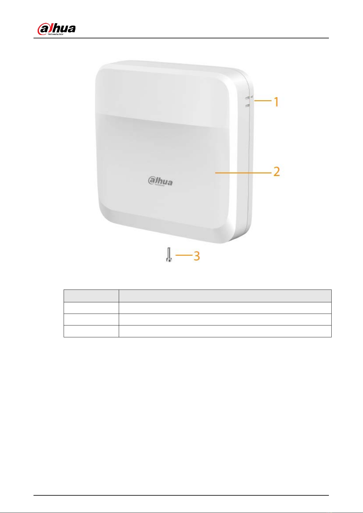
Figure 1-2 Front view
Table 1-1 Components description
No. Description
1 Guiding mark
2 Front panel
3 Screw
Quick Start Guide
3
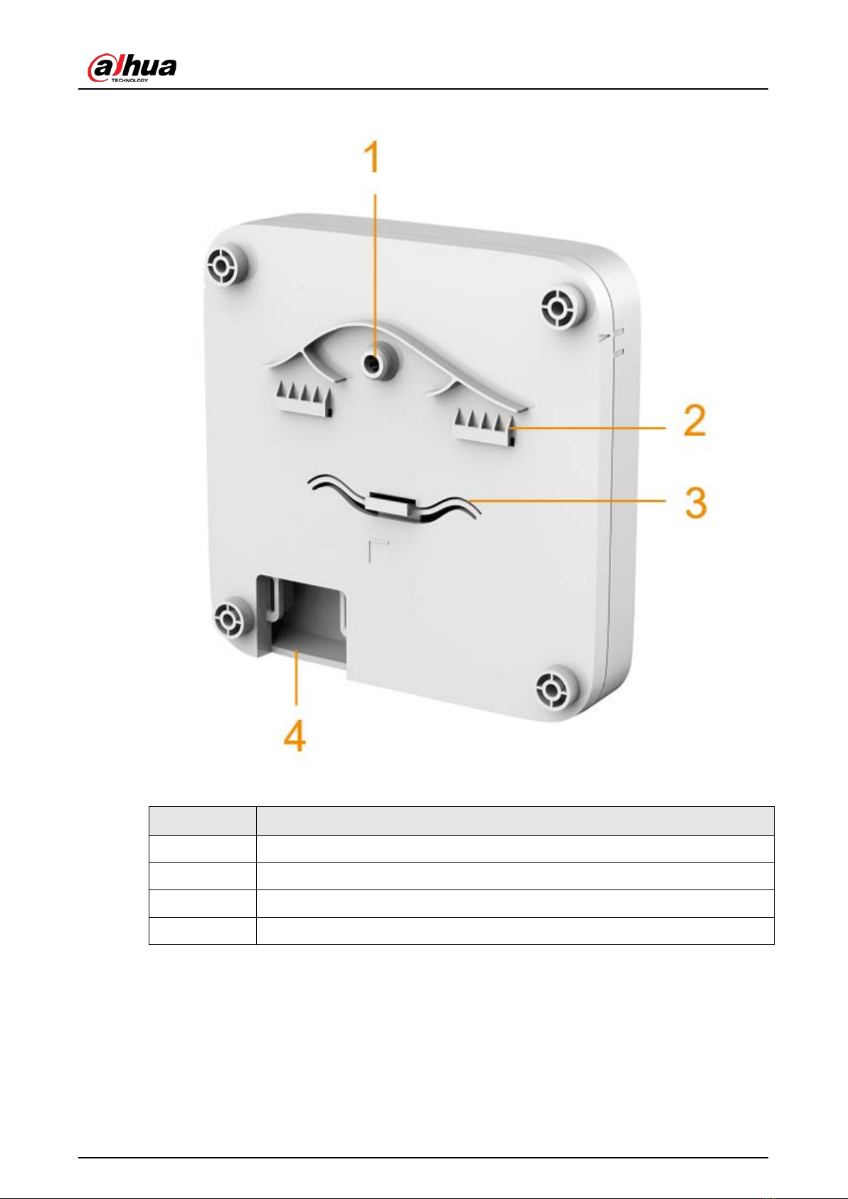
Figure 1-3 Back cover
Table 1-2 Back cover description
No. Description
1 Tamper alarm switch
2 Upper DIN clip
3 Lower DIN clip
4 Wiring outlet

Quick Start Guide
4
2 Ports Overview
Figure 2-1 Ports
Table 2-1 Ports description
No Name Description
1 READER1 Reader connector
2 READER2 Reader connector
3 AUX Auxiliary connector (including door detector, door exit button,
and alarm input)
4 DC IN Power connector
5 ALM_OUT Alarm output connector
6 RJ45 Network connector (PoE)
7 — Tampering alarm switch
8 — Reset button
9 RELAY Relay connector
10 LOCK Power lock connector
11 STATUS LED indicator
12 RS485 RS485 connector (not used)
13 AUDIO Audio connector (not used)
Table des matières
Autres manuels Dahua Technology Contrôleurs d'accès IP


