Daewoo AGC-2208RDS Manuel utilisateur

Service Manual
Car Audio
S/M No : AGC2208EF0
MODEL : AGC - 2208 / 2218 Series
2208 Series 2218 Series
DAE OO ELECTRONICS CO., LTD
Email: [email protected] Sep. 2003
MP3 CD, CD Player
Flip-Dow Detachable Face for A ti-Theft
4-Cha el high Power (40W x 4Ch)
Electro ic Volume/Bass/Treble/Bala ce/Fader
Co trol
Electro ic Tu i g
42 Memory Capability (18FM+12MW+12LW)
Local/DX Switch
Loud ess & Mute Co trol
10 CD-cha ger co trol (Optio )
AGC-2208RDS
AGC-2208BASIC
AGC-2206RDS
AGC-2206BASIC
AGC-2218RDS
AGC-2218BASIC
AGC-2216RDS
AGC-2216BASIC

TABLE OF CONTENTS
1. PRODUCT SPECIFICATION
2. LINE DRA ING
3. EMERGENCY TROUBLE SHOOT
4. CD PART
5. SCHEMATIC DIAGRAM
6. PARTS LOCATION ON P.C.BOARD
7. OVERALL EXPLODED VIE & PARTS LIST
8. DECK MECHANISM EXPLODED VIE & PARTS LIST
9. ELECTRICAL PARTS LIST
10. FUNCTION OF MICOM IC
11. IC BLOCK DIAGRAM
12. LIQUID CRYSTAL DISPLAY
13. OUTPUT CONNECTION DESCRIPTIONS
1
2
3
6
8
9
13
15
16
23
25
32
33
--------------------------------
--------------------------------
--------------------------
--------------------------------
--------------------------------
--------------------------
---------
---
--------------------------------
--------------------------------
--------------------------------
--------------------------------
-----------------

1
1. PRODUCT SPECIFICATIONS
AUDIO SECTION
Maximum output power : 40watts per channel into 4 ohms.
Load impedance : 4 ohms or 8 ohms
Total harmonic distortion : Less than 10% at 14 watts
Frequency response : 100Hz(±3dB), 20kHz(±3dB)
Control Bass/Treble : 10±3dB at 100Hz/10kHz
CD PLAYER SECTION
Total harmonic distortion : 0.1%
Signal to noise ratio : 80dB
Laser Diode Properties : Meterial - GaAlAs
Wave length - 775~800 nm
Laser output Power - Less than 400 uW
TUNER SECTION
(FM) Tuning range : 87.5 to 108MHz
Sensitivity : 10dBuV
Stereo separation : 30dB
Signal to noise ratio
:
60dB
(MW) Tuning range : 522 to 1620KHz at Europe
( 530 to 1710kHz at U.S.A)
Sensitivity : 22dBuV
Signal to noise ratio
:
50dB
Channel space : 9KHz (or 10KHz at U.S.A)
(LW) Tuning range : 144 to 288KHz
Usable Sensitivity : 25dBuV
GENERAL
Power requirements : DC 13.8V (10.8 ~15.6V allowable)
Negative ground
Speaker impedance : 4 or 8 ohm
Output power : Maximum 40Wx4Ch.
Current consumption : 10A (MAX)
Dimension (W x H x D) : 178 x 50 x 156 mm
Chassis size : 195 x64 x14.6 mm
Weight(Net) : 1.48Kg
Design and specifications are subject to changes for improvements without notice.
2
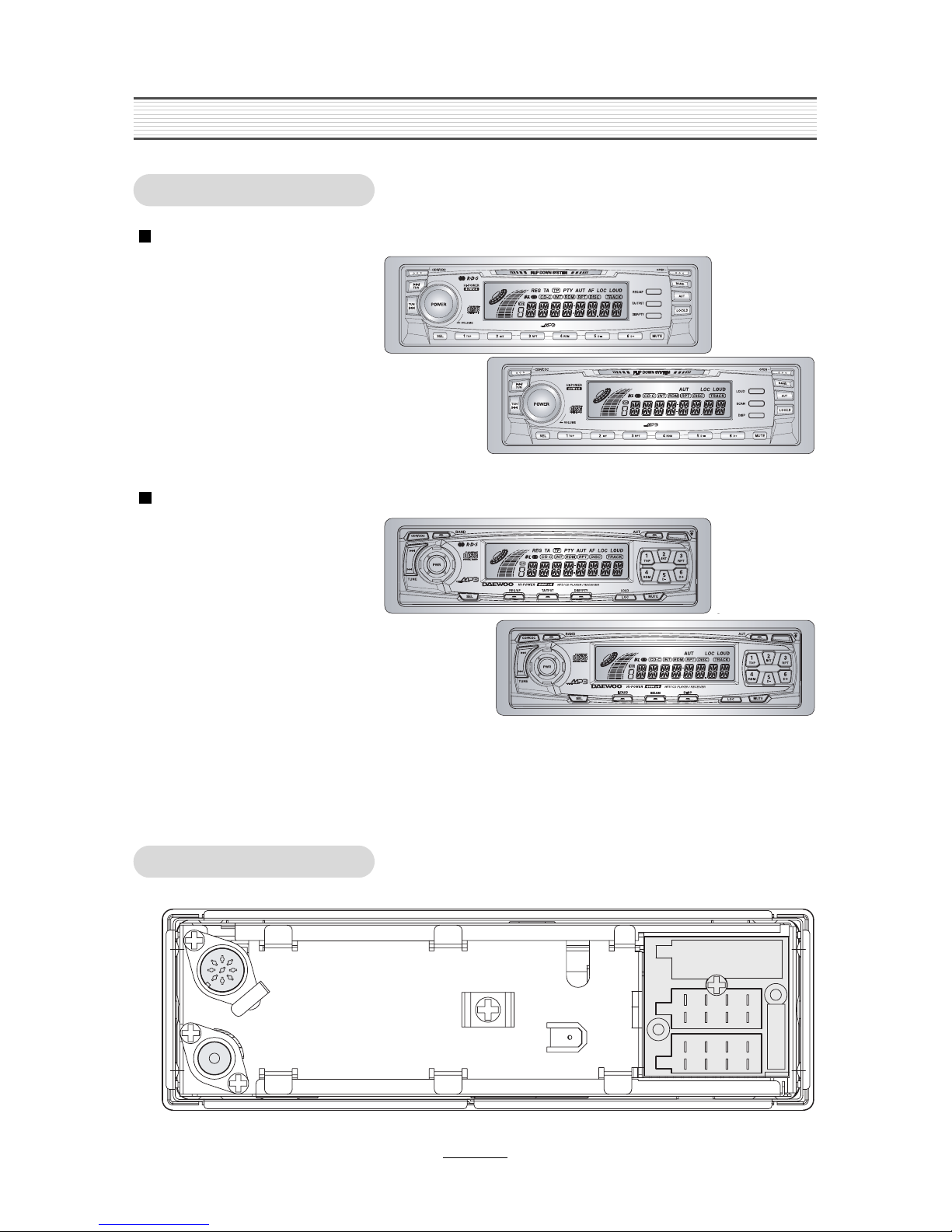
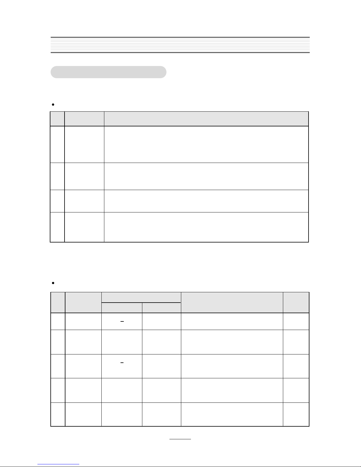
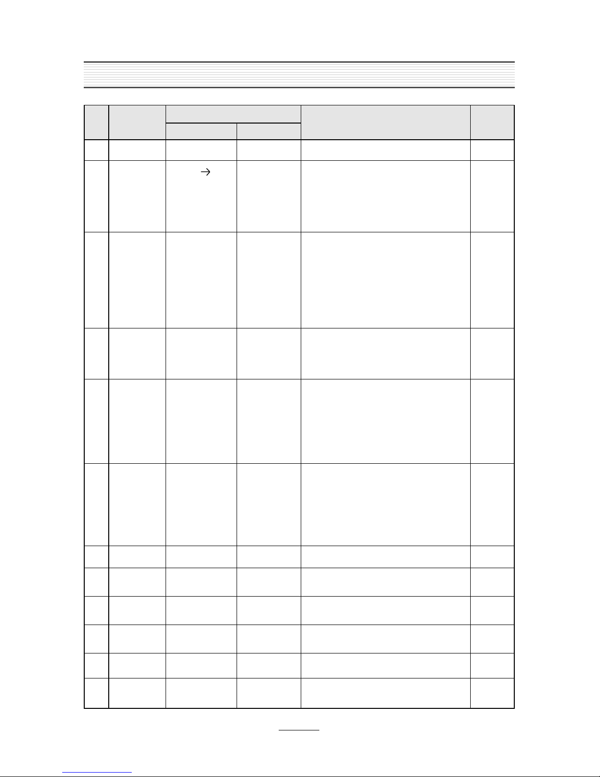
2. LINE DRA ING
2-1. FRONT SIDE
2-2. REAR SIDE
AGC-2208 Series (RDS & BASIC Function)
- RDS or No RDS Fu ctio
- MP3, Compact Disc Player
- Flip-Dow Detachable Face for A ti-Theft
- 4-Cha el high Power (40W x 4Ch)
- Electro ic Volume /Bass /Treble /Bala ce
/Fader Co trol
- Electro ic Tu i g
- 42 Memory Capability (18FM+12MW+12LW)
- Local/DX Switch
- Loud ess & Mute Co trol
- 10 CD-cha ger co trol (Optio )
AGC-2218 Series (RDS & BASIC Function)
- RDS or No RDS Fu ctio
- MP3, Compact Disc Player
- Flip-Dow Detachable Face for A ti-Theft
- 4-Cha el high Power (40W x 4Ch)
- Electro ic Volume /Bass /Treble /Bala ce
/Fader Co trol
- Electro ic Tu i g
- 42 Memory Capability (18FM+12MW+12LW)
- Local/DX Switch
- Loud ess & Mute Co trol
- 10 CD-cha ger co trol (Optio )

3
3. EMERGENCY TROUBLE SHOOT
3-1. General Function
No sound from
speakers
Yes
No
Yes
Output connector
is missing
Output connector
is inferior goods
Put exactly output
connector in.
Change output
connector to
superior goods
Yes
No
Power IC, Output
Socket is inferior
goods
Change Power IC,
Output Socket to
superior goods
Yes
A
A
L.C.D or Lamp
is not turned
off.
Yes
No
Yes
Power is not
supplied Return to
Output voltage of
power IC is little.
Change Regulator
IC and check
output voltage.
Yes
No
LCD or Lamp is
inferior goods.
Change LCD or
Lamp to superior
goods.
Yes
Different each
channel have
output level
(Front, Rear,
Left, Right)
Treble or Bass
is low
unusually
Yes
No
Yes
Balance of front
and rear is in one
side
Balance of Left,
Right is in one
side.
Re-adjust Balance
of front, rear
Ref.
Bala ce = Ce ter
Fro t / Rear
Ref.
Bala ce = Ce ter
Left / Right
Ref.
Bala ce = Ce ter
Treble / Bass
Ref.
Regulator IC output
Voltage = V
Ref.
Electrical Parts List
L.C.D., Lamp
Re-adjust Balance
of Left, Right
Yes
Yes
Balance of Treble
or Bass is in one
side.
Re-adjust Balance
of Treble or Bass
Yes

4
EMERGENCY TROUBLE SHOOT
3-2. Tuner Function
Hearing noise
only
Yes
No
Yes
No selected the
station
Tuner Module is
inferior goods.
Select exactly
broadcasting
frequency.
Change tuner
module to
superior goods.
Yes
Weak frequency
area caused by
elevations
Change to goods of
R.D.S function.
Yes
A
B
A
Station in
other regions
are not held.
Yes Yes
No selected the
local stations. Return to or
Extreme noise
in broadcast
Weak
separation of
FM stereo
Yes
No
Yes
Antenna
connector is
missing
Put exactly
antenna connector
in his jack
Ref.
Adjustme ts/Tu er
Fu ctio of auto-
switch oise
reductio
Ref.
Yes
Weak frequency
area of FM, MW
Switch
automatically to
mono mode in
weak frequency
area
Yes
B
R1 I case of located Glass A te a, check if heat wire is cut or ot i rear wi dow.
R2 Check A te a co ector part.

EMERGENCY TROUBLE SHOOT
5
Disc is not
inserted.
Yes Yes
There is Disc in
the slot
Take out Disc
from the slot
Disc is inferior
goods
Use only superior
disc
No
Yes
A
Selection time
is longer than
unusually
Yes
Selected PAUSE
function
Release PAUSE
function
Yes
Selected MUTE
function
Release MUTE
function
Yes
Mechanism is
inferior goods
Change
Mechanism to
superior goods
Turn power on
again after turn off.
Yes
Inspect disc for
scratches.
Yes
No sound
Yes
No
Yes
disc was inserted
upside down
Insert CD with
label side down
Ref.
DWEC CD Mecha
DCM-400B
Ref.
Power Off/O
Hard Reset
No
No
No
Disc is dirty
Wipe with cleaning
cloth
Yes
A
Ref. Point
Disc is stopped
under eject
Yes
It is normal for
CD-Deck or the
slot
Yes
3-3. CD Function
6
Defi itio of Mecha ical Mode
No
1
2
3
4
STOP MODE
LOADING
MODE
PLAY MODE
EJECT
MODE
- Disc have ’t bee i serted or disc have bee ejected. Whe disc shall be tra sported
i to the u it
Mecha ism shall be fixed at this mode.
- Loadi g device ca i sert disc thru the slot.
- Floati g device bei g locked.
- Disc have bee i serted thru the slot i fro t of u it. It is tra sie t state betwee STOP
mode a d PLAY mode.
- If disc should be i serted at the state of POWER ON, disc shall be loaded by a series of
operatio of specified device.
- After disc have bei g clamped o the tur -table, disc shall be rotated.
- Disc shall be played.
- Floati g device bei g u locked.
- Disc is to be ejected at this mode. It is tra sie t state betwee PLAY mode a d STOP
mode.
-
If disc should be mou ted at the state of POWER ON a d comma ded by EJECT key, disc
shall be ejected thru the slot by a series of operatio of specified device.
MODE DEFINITION & STATUS
Sta dard values / Play-ability test
No
1
2
3
4
5
Loadi g Time
Ejecti g Time
Access Time
Disc
Take-up Force
Disc
7sec + 3sec
6sec + 3sec
<
17 sec
<
15 sec
<
15 sec
<
5 sec
> 120g
> 120g
> 80g
> 90g
Duri g play i
low temp.
> 70g
Duri g play i
low temp.
From i sertio up to make sou d.
(TCD-784)
From track No.1 Betwee the EJECT
comma d a d the disc eject completio .
(TCD-784)
From out-most Track, Betwee the PLAY
comma d of i -most Track a d marki g
sou d.
Shall be measure whe the ce ter of Disc is
correspo d with the ce ter of Roller.
Shall be measure whe the ce ter of Disc is
correspo d with the ce ter of Roller.
ITEMS
CONNEC
TION
SPECIFIED VALUES, CONDITIONS
STANDARD VALUES RELIABILITY LIMITS
TEST CONDITIONS, REFERENCES
CDP MODE & PLAYABILITY
4. CD PART
7
No
8
9
10
11
12
13
14
15
16
17
A ti-Vibratio al
Performa ce
Playability
Disc Deflectio
Disc
Ecce tricity
Jitter
Freque cy
Respo se
Harmo ic
Distortio
Dy amic
Ra ge
S/N Ratio
Cha el
+ 0.4mm
+ 0.21mm
< 28 sec
< 0.03% at 1kHz
> 80dB at 1kHz
> 85dB at 1kHz
> 70dB at 1kHz > 65dB at 1kHz
> 85dB at 1kHz
> 75dB at 1kHz
< 0.05% at 1kHz
20-20kHz + 2dB 20-20kHz + 3dB
< 33 sec
+ 0.21mm
+ 0.4mm
equal with
sta dard values
-I terruptio :0.7mm
-Block Dot Disc:0.8mm
-Scratch Disc:1mm
-
Fi ger Pri t Disc:65um
>1.0g/10Hz-20Hz, Z way
>2.0g/30Hz-200Hz, Z way
>0.6g/10Hz-20Hz, X&Yway
>1.2g/30Hz-200Hz, X&Yway
X=side to side
Y=fro t to back
Z=up to dow
Z way o ly
10Hz-20Hz:0.7g
30Hz-200Hz:1.2g
-The G level should be upped to the sou d
skip level from the less level slowly at the
freque cy.
-Ig ore the sou d skip at the ear of
reso a ce freque cy(about 100Hz).
-I playi g YEDS-10 Tr #5, shall perform with
vibratio
-No sou d skippi g.
-No sou d skippi g i the specified ra ge.
-The sou d skippi g does ot i clude a y
i terpolati g oise.
-No sou d skippi g at the ABEX 731RA Tr
No8
-The sou d skippi g does ot i clude a y
i terpolati g oise.
-Except from specified item due to the
reliability limits of TEST DISC i the HTO
TEST.
-No sou d skippi g at the ABEX 713 Tr No8
-The sou d skippi g does ot i clude a y
i terpolati g oise.
-Except from specified item due to the
reliability limits of TEST DISC i the HTO
TEST.
This measureme t may be do e at 20Hz,
20kHz, (1kHz=0dB)
400Hz HIGHPASS FILTER
20kHz(-60dB 24kHz) LOWPASS FILTER
20kHz(-60dB 24kHz) LOWPASS FILTER,
60dB AMP IHF-A WEIGHTING FILTER
400Hz HIGHPASS FILTER
20kHz (-60dB 24kHz)LOWPASS FILTER
ITEMS
CONNEC
TION
SPECIFIED VALUES, CONDITIONS
STANDARD VALUES RELIABILITY LIMITS
TEST CONDITIONS, REFERENCES
7
Mecha ical
Noise
Loadi g Eject
< 75dB(A)
Play < 40dB(A)
Access < 70dB(A)
If a ythi g is ot
error, shall ot
defi ed.
-Test should be performed i o reverberatio
room at the oise level of less tha 20dB(A).
-Test should be performed at the 50cm i fro t
of the u it.
-IHF-A MODE (RMS-FAST)(TCD-792D)
6
Clampi g Force
> 130g > 130g
CD PART

6-1. PCB MAIN / AGC-2208, 2218 Series
9
6. PARTS LOCATION ON P.C. BOARD
PART SIDE
Ce manuel convient aux modèles suivants
7
Table des matières
Autres manuels Daewoo Système stéréo de voiture

Daewoo
Daewoo AKF-8846 Manuel utilisateur

Daewoo
Daewoo AKR-0106A Manuel utilisateur

Daewoo
Daewoo CDP-0206R Manuel utilisateur

Daewoo
Daewoo AKD-0105 Series Manuel utilisateur

Daewoo
Daewoo AKF-8846 Manuel utilisateur

Daewoo
Daewoo AKF-0275 Series Manuel utilisateur

Daewoo
Daewoo AKR-0108 Series Manuel utilisateur


