Cytron Technologies SmartDrive40 Manuel utilisateur

ROBOT . HEAD to TOE
Product User’s Manual – MDS40B
INDEX
1. Introduction 3
2. Packing List 4
3. Product Specifications 5
4. Board Layout 6
5. Power Supply 9
6. Motor Connection 10
7. Safety Features 11
8. Input Modes 12
a. RC Input Mode 14
b. Analog/PWM Input Mode 16
c. Simplified Serial Mode 18
d. Packetized Serial Mode 20
9. Warranty 22
Created by Cytron Technologies Sdn. Bhd. – All Rights Reserved 2

ROBOT . HEAD to TOE
Product User’s Manual – MDS40B
1. INTRODUCTION
Enhanced SmartDrive40 is an enhancement version of SmartDrive40 which is designed to
drive medium to high power brushed DC motor with current capacity up to 80A peak and
40A continuously. MOSFETs are switched at 16 KHz to ensure quiet operation and no
annoying whining sound. Besides, it also equipped with a microcontroller unit to provide
smart features such as multiple input mode, current limiting and thermal protection.
Enhanced SmartDrive40’s feature makes driving a robot with differential drive a truly plug
and play experience.
Some of the features for Enhanced SmartDrive40 are summarized as below:
●Bi-directional control for dual brushed DC motor.
●Support motor voltage from 10V to 45V.
●Maximum current up to 80A peak (1 second), 40A continuously.
●On board MOSFETs are switched at 16 KHz for quiet operation.
●Battery low voltage indicator.
●Battery over voltage indicator.
●Thermal protection.
●Multiple input modes: RC, Analog, PWM, Simplified Serial and Packetized Serial.
●On board push buttons for fast test and manual operation.
●No polarity protection for V motor.
Created by Cytron Technologies Sdn. Bhd. – All Rights Reserved 3

ROBOT . HEAD to TOE
Product User’s Manual – MDS40B
2. PACKING LIST
Please check the parts and components according to the packing list. If there are any parts
missing, please contact us at [email protected] immediately.
●1 x Enhanced SmartDrive40 with top and bottom cover.
●2 x 2561 Servo Extension cable
Created by Cytron Technologies Sdn. Bhd. – All Rights Reserved 4
ROBOT . HEAD to TOE
Product User’s Manual – MDS40B
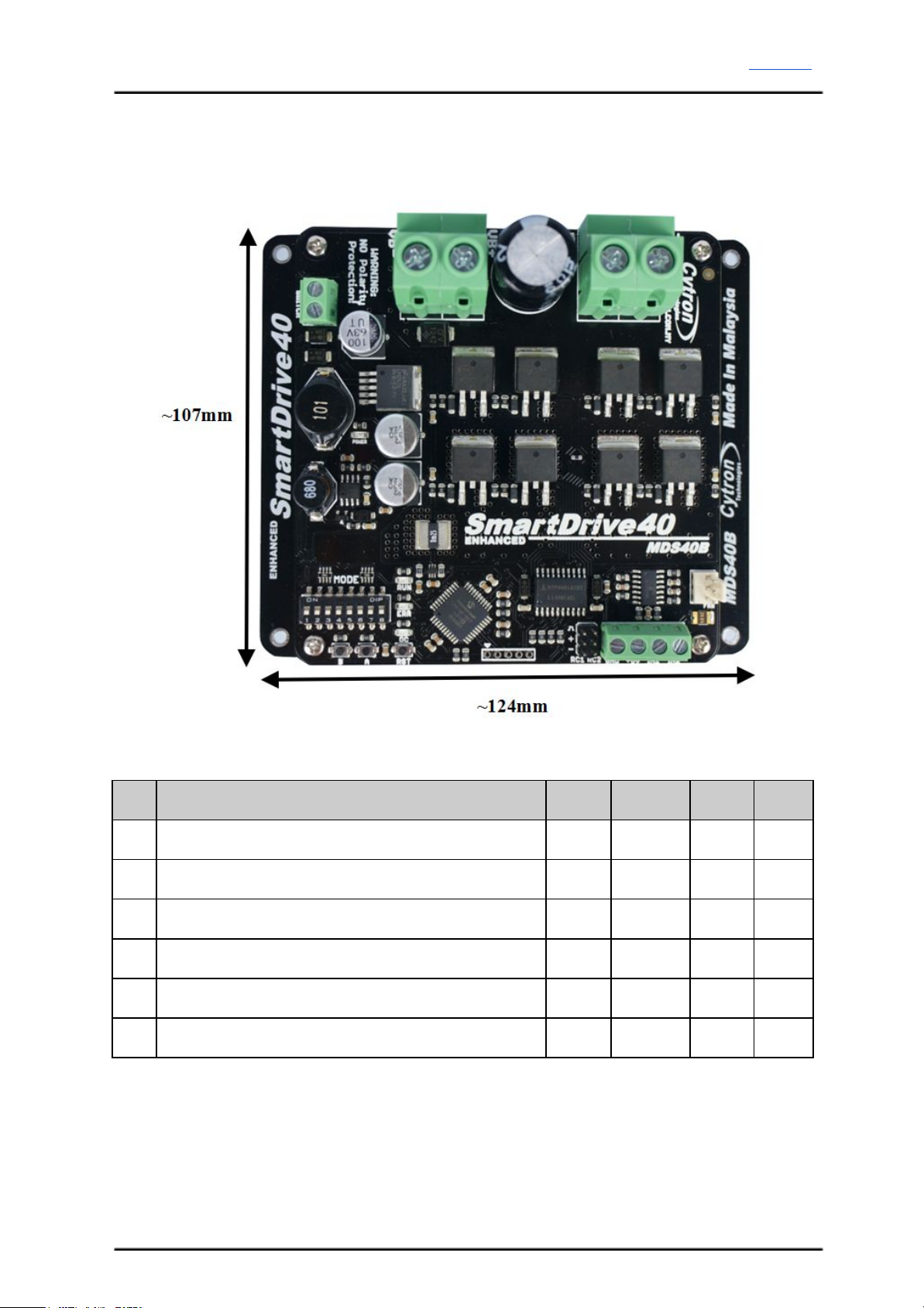
3. PRODUCT SPECIFICATIONS
Dimension:
Absolute Maximum Rating of Enhanced SmartDrive40
No
Parameters
Min
Typical
Max
Unit
1
Input Voltage (Motor Supply Voltage)
10
-
45
V
2
IMAX (Maximum Continuous Motor Current)*
-
-
40
A
3
IPEAK – (Peak Motor Current) **
-
-
80
A
4
VIOH (Logic Input – High Level)
1.3
-
5
V
5
VIOL (Logic Input – Low Level)
0
-
0.7
V
6
5V Output Current
-
-
500
mA
* Depends on the room temperature.
** Must not exceed 1 second.
Created by Cytron Technologies Sdn. Bhd. – All Rights Reserved 5

ROBOT . HEAD to TOE
Product User’s Manual – MDS40B
4. BOARD LAYOUT
Label
Function
A
Power Supply Terminal block
B
Motor Terminal Block
C
Motor LED Indicator
D
Fan Input Pin
E
Analog/PWM/Serial Input Terminal Block
F
RC Input Pin
G
Reset Button
H
Motor Test Button
I
Motor Test Button
J
Run LED
K
Error (ERR) LED
L
Mode Selection DIP Switch
M
Power Switch Terminal Block
Created by Cytron Technologies Sdn. Bhd. – All Rights Reserved 6

ROBOT . HEAD to TOE
Product User’s Manual – MDS40B
FUNCTION Description:
Motor Terminal Block
Connect to motor at your mobile robot. User can screw to lock the wire to the terminal block
or solder the wire directly to the pad at bottom layer. Please use wire with proper thickness to
support the expected current.
Power Supply Terminal Block
Connect to power source. User can screw to lock the wire to the terminal block or solder the
wire directly to the pad at bottom layer. No polarity protection, please double check before
power up. Please use wire with proper thickness to support the expected current.
MotorLED Indicator
Indication for current flow and direction for motor. If LED A turns on, means current flows
from output A to B. Vice versa.
Power Switch Terminal Block
Switch for power up MDS40B’s microcontroller and logic circuit. This switch is ON by
default.
Run and Error LED
Run LED will turn on when motor is running.
Error LED
Number of Blinks
Error
Description
Off
No Error
No error has been detected.
2
Input Error
Invalid or no input detected.
3
Under Voltage
The battery voltage is low.
4
Over Voltage
Supply voltage is over the limit. MDS40B
will not operate.
5
Over Temperature
Board temperature is high.
Test Button
Fast test to check driver functionality for motor. If A is pressed, current flows from output A
to B. Vice Versa.
Mode Selection DIP Switch
User can select different input mode by setting the DIP switch.
RC Input Pin
This pins specially for RC receiver input wire. RC1 for forward/reverse and RC2 for steering.
Created by Cytron Technologies Sdn. Bhd. – All Rights Reserved 7

ROBOT . HEAD to TOE
Product User’s Manual – MDS40B
Analog/PWM/Serial Input Terminal Block
No
Pin Name
Description
1
GND
Ground.
2
5V
+5V output. Do not connect to another 5V source.
3
IN1
Input 1.
4
IN2
Input 2.
*Please refer to INPUT MODE section for more detail.
Created by Cytron Technologies Sdn. Bhd. – All Rights Reserved 8

ROBOT . HEAD to TOE
Product User’s Manual – MDS40B
5. POWER SUPPLY
Enhanced SmartDrive40 supports input voltage ranges from 10V to 45V. The recommended
power sources are:
●6 – 18 cells NiMH or NiCd battery.
●3 – 6 cells LiPo or Li-Ion battery.
●10V – 45V sealed lead acid battery.
●10V – 45V power supply (Must be in parallel with a battery with same voltage).
The power source can be connected to Enhanced SmartDrive40 either via the terminal block,
or soldered directly to the pad at the bottom layer. There is no polarity protection on
MDS40B, please double check the connection before connecting to power source.
NOTE:
1. If a power supply that cannot sink current is being used (example: bench top and AC to
DC switching power supply), the input voltage will rise when the driver is regenerating
(motor is slowing down). Thus, it is important to connect a battery with same voltage in
parallel with the power supply to absorb the current generated by the motor. Else, the
input voltage might rise to a level where Enhanced SmartDrive40 will be destroyed
permanently or the power supply trigger protection mode.
Created by Cytron Technologies Sdn. Bhd. – All Rights Reserved 9

ROBOT . HEAD to TOE
Product User’s Manual – MDS40B
6. MOTOR CONNECTION
Similar to the power supply, connection to the motor can be made either via the terminal
block, or it can be soldered directly to the bottom layer pad.
For Mixed mode, especially for RC input mode (or Breakout board with Joystick soldered),
each terminal block must be connected to the same side of the motor. For example, left
terminal block connected to motor LEFT and right terminal block connected to motor
RIGHT. User can further test it by controlling the motor by using RC controller. If the motor
give wrong direction, reverse the polarity of the motor connection at the terminal block.
Created by Cytron Technologies Sdn. Bhd. – All Rights Reserved 10
Autres manuels pour SmartDrive40
1
Ce manuel convient aux modèles suivants
1
Table des matières
Autres manuels Cytron Technologies Entraînement CC


Manuels Entraînement CC populaires d'autres marques

Vincent Associates
Vincent Associates UNIBLITZ ED12DSS Manuel utilisateur

EKSMA OPTICS
EKSMA OPTICS DQ-100-4 Manuel de la liste des pièces

Chamberlain Garog
Chamberlain Garog D Series Manuel utilisateur

Parker
Parker PDS Series Manuel utilisateur

Festo
Festo DGC G Series Guide de configuration

Binks
Binks QS-5012-1-CE Manuel utilisateur


