Crossbow Technology CXM539 Manuel utilisateur

Crossbow Technology, Inc., 41 E. Daggett Dr., San Jose, CA 95134
Tel: 408-965-3300, Fax: 408-324-4840
CXM539 User’s Manual
High Speed Digital 3-Axis Fluxgate
Magnetometer
Revision 1.2 October 2001
PN 6001-0014
SUNSTAR传感与控制 http://www.sensor-ic.com/ TEL:0755-83376549 FAX:0755-83376182 E-MAIL:[email protected]m
SUNSTAR自动化 http://www.sensor-ic.com/ TEL: 0755-83376489 FAX:0755-83376182 E-MAIL:[email protected]

©1999-2000 Crossbow Technology, Inc. All rights reserved. Information
in this document is subject to change without notice.
Crossbow and SoftSensor are registered trademarks and DMU is a
trademark of Crossbow Technology, Inc. Other product and trade names
are trademarks or registered trademarks of their respective holders.
SUNSTAR传感与控制 http://www.sensor-ic.com/ TEL:0755-83376549 FAX:0755-83376182 E-MAIL:[email protected]m
SUNSTAR自动化 http://www.sensor-ic.com/ TEL: 0755-83376489 FAX:0755-83376182 E-MAIL:[email protected]

Table of Contents
1Description of the System.....................................................1
2System Specifications ...........................................................2
3Electrical and Mechanical Interface.....................................3
4System Startup and Checkout..............................................5
4.1 Startup Using a Terminal Emulator Program.....................................5
4.2 System Checkout.....................................................................................6
5CXM539 Configuration Options and Data Output Formats 8
6Appendix A. CXM539 command spec................................11
6.1 Main Commands (available in all modes)........................................11
6.2 Calibration Commands (only available in config mode)...............12
6.3 EEROM Map.........................................................................................12
6.4 Software Data Correction Equations.................................................14
7Appendix B. Filter Values and Data Rates.........................15
8Appendix C. Warranty and Support Information..............16
8.1 Customer Service ..................................................................................16
8.2 Contact Directory..................................................................................16
8.3 Return Procedure...................................................................................16
8.4 Warranty.................................................................................................17
SUNSTAR传感与控制 http://www.sensor-ic.com/ TEL:0755-83376549 FAX:0755-83376182 E-MAIL:[email protected]m
SUNSTAR自动化 http://www.sensor-ic.com/ TEL: 0755-83376489 FAX:0755-83376182 E-MAIL:[email protected]

About this Manual
The following annotations have been used to provide additional
information.
XNOTE
Note provides additional information about the topic.
þEXAMPLE
Examples are given throughout the manual to help the reader understand the
terminology.
PIMPORTANT
This symbol defines items that have significant meaning to the user
MWARNING
The user should payparticular attention to this symbol. It means there is a
chance that physical harm could happen to either the person or the
equipment.
The following paragraph heading formatting is used in this manual:
1 Heading 1
1.1 Heading 2
1.1.1 Heading 3
Normal
SUNSTAR传感与控制 http://www.sensor-ic.com/ TEL:0755-83376549 FAX:0755-83376182 E-MAIL:[email protected]m
SUNSTAR自动化 http://www.sensor-ic.com/ TEL: 0755-83376489 FAX:0755-83376182 E-MAIL:[email protected]

CXM539 User’s Manual
Doc.# 6001-0014 Rev1.2Page 1
1Description of the System
The model CXM539 High Speed Digital 3 Axis Fluxgate Magnetometer is
the first high-speed digital output 3-axis fluxgate magnetometer to be
commercially available. The system can convert and transmit over its serial
port (at 38400 baud) all three axes outputs at a rate of 250 samples per
second. Slower data rates can also be selected; transmission rate and baud
rates are user programmable. The CXM539 uses 3 separate 16-bit sigma
delta analog to digital (A to D) converters to achieve the high throughput.
The scale factor is set so that a full scale input of 10-4T (1 G) represents
32768 counts on the system A to D converters. The least count represents
about 3 nT. Noise of the system is 1 -2 counts.
The CXM539 system is ideallysuited to situations where high speed
magnetic data must be acquired and analyzed. In the past, such systems
have normally used a combination of an analog output fluxgate and an A to
D board in a PC. The CXM539 simplifies and reduces the cost of the
magnetic data acquisition system by eliminating the cumbersome A to D
board.
The CXM539 can be used in either a command mode or autosend mode. In
the command mode, the CXM539 responds to commands to transmit data
issued by an external computer. In the autosend mode, the CXM539
commences sending data as soon as power is applied to the unit.
The CXM539 can be supplied with an optional connector box, which allows
easy powering and connection to an external computer.
SUNSTAR传感与控制 http://www.sensor-ic.com/ TEL:0755-83376549 FAX:0755-83376182 E-MAIL:[email protected]m
SUNSTAR自动化 http://www.sensor-ic.com/ TEL: 0755-83376489 FAX:0755-83376182 E-MAIL:[email protected]

CXM539 User’s Manual
Doc.# 6001-0014 Rev1.2Page 2
2System Specifications
Accuracy ±0.1 µT (±1 mGauss)
Noise level ±0.003 µT (±0.03 mGauss)
Range ±100 µT (±1 Gauss)
Scale stability ±.05% FS/°C
Initial offset <±200 nT (±2 mG)
Offset vs. temp <5 nT/°C (<0.05 mG)
Orthogonality of axes better than ±0.5°
Alignment of axes with package better than ±0.5°
Linearity ±0.1% full scale
Maximum data transfer speed(38,400 baud) 250 -3 -axis samples/sec
Power 100 ma @ +6 to +15 VDC
A to D 3 -16 bit Sigma Delta
Baud rate (user selectable) 300, 1200, 2400, 4800, 9600,
19200, 38400, 72800
Temperature range -25 to 70°C
Size 1.60”W x 4.08”L x 1.13”H
4 cm x 10.4 cm x 2.9 cm
Connector 9 pin nonmagnetic “D”
(female)
SUNSTAR传感与控制 http://www.sensor-ic.com/ TEL:0755-83376549 FAX:0755-83376182 E-MAIL:[email protected]m
SUNSTAR自动化 http://www.sensor-ic.com/ TEL: 0755-83376489 FAX:0755-83376182 E-MAIL:[email protected]

CXM539 User’s Manual
Doc.# 6001-0014 Rev1.2Page 3
3Electrical and Mechanical Interface
The CXM539 is powered from a single inputvoltage that can range
between +6 V and +15 V. Current consumption is 100 ma. Two serial
interfaces are present; one that uses RS-232 levels and one that uses TTL
levels. The baud rate is user programmable and can be set at the following
values: 300, 1200, 2400, 4800, 9600, 19200, 38400, and 72800. The data
words employ 8 bits with one stop bit and no parity.
A female 9 pin D connector is used to provide an electrical interface to the
CXM539 system. The Pin out of this connector is as follows:
Pin Function
1not used
2RS 232 out
3RS 232 in
4not used
5ground
6TTL serial out
7TTL serial in
8configure
9+ V in (+7.5 V to +15 V)
A drawing showing the dimensions and mounting hole design of the
CXM539 is shown belowin Fig. 1.
SUNSTAR传感与控制 http://www.sensor-ic.com/ TEL:0755-83376549 FAX:0755-83376182 E-MAIL:[email protected]m
SUNSTAR自动化 http://www.sensor-ic.com/ TEL: 0755-83376489 FAX:0755-83376182 E-MAIL:[email protected]

CXM539 User’s Manual
Doc.# 6001-0014 Rev1.2Page 4
4X 16
Φ
4.08”
(10.4 cm)
1.60”
(4 cm)
3.70”
(9.4 cm)
1.10”
(2.8cm)
4.08”
(10.4 cm)
3.32” (8.4 cm)
1.125”
(2.9 cm)
1
Fig. 1 CXM539 High Speed Digital 3 Axis Fluxgate Magnetometer
SUNSTAR传感与控制 http://www.sensor-ic.com/ TEL:0755-83376549 FAX:0755-83376182 E-MAIL:[email protected]m
SUNSTAR自动化 http://www.sensor-ic.com/ TEL: 0755-83376489 FAX:0755-83376182 E-MAIL:[email protected]

CXM539 User’s Manual
Doc.# 6001-0014 Rev1.2Page 5
4System Startup and Checkout
4.1 Startup Using a Terminal Emulator Program
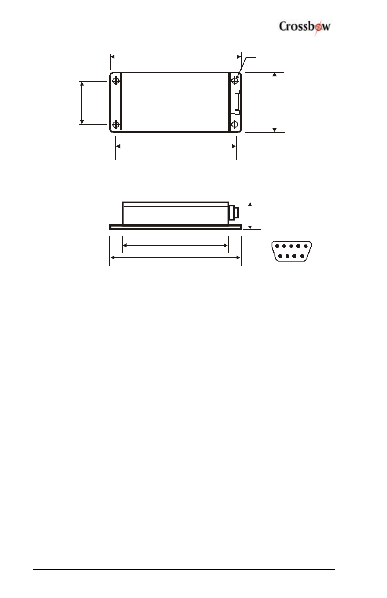
Connect the CXM539 to the connection box using the supplied ribbon cable
(use 9 pin male on connection box). Connect a cable from a serial port on a
PC to the connection box (use 9 pin female on connection box). Select the
AUTO option on the connection box switch. This connects pin 1 (CD) of
the 9 pin serial interface connector to the configure port on the CXM539.
Note that on the 9 pin computer connector, pins 1, 4 and 6 are shorted and
pins 7 and 8 are shorted). Connect a power supply (+7.5 V to +15 V) to the
red (positive) and black banana plug on the connection box.
Alternatively, according to the I/O pin functions described in Chapter 3, use
the RS-232 interface when connecting to a PC com port.
Start up a terminal emulator program on the PC, e.g. Windows
HyperTerminal, PC Plus, etc. Configure the terminal emulator program for
direct connect toan available com port and select the baud rate 9600 with
one stop bit and no parity. On the electrical interface to the system ground
pin 8; this will put the system in configure mode and assure that the baud
rate is 9600 baud. If a connection box is used, select the “config” option on
the connector box switch.
Apply power to the system and check to see that the unit transmits a start up
message:
APS 539 V1.12 Config. Mode
The system can now be configured for operation in various modes as
described in Appendix A by issuing commands over the serial interface.
After configuring the CXM539 system, ungrounded pin 8. If a connector
box is used, select the “Run” option in the connector box switch. In run
mode, the CXM539 sign on message sent at power on is
APS 539 V1.12.
SUNSTAR传感与控制 http://www.sensor-ic.com/ TEL:0755-83376549 FAX:0755-83376182 E-MAIL:[email protected]m
SUNSTAR自动化 http://www.sensor-ic.com/ TEL: 0755-83376489 FAX:0755-83376182 E-MAIL:[email protected]

CXM539 User’s Manual
Doc.# 6001-0014 Rev1.2Page 6
In run mode, most of the CXM539 parameters, e.g. baud rate, sample rate,
etc. can be set by the user. The main differences between the system
operation in run and configure mode are as follows:
1. The CXM539 can only be calibrated in config mode (by issuing
the l command). The unit is always factory calibrated and
recalibration by the user is not normally required.
2. The unit always starts in the (known) baud rate of 9600 baud.
3. The unit always starts in command mode (as opposed to autosend
mode).
4. The data output format is selected to be A to D count mode.
The main functions of the config mode are to assure that the CXM539
communicates using a known baud rate (9600) and to enable calibration of
the system.
MWARNING
Always operate the CXM539 in run mode (when using a terminal program)
unless the baud rate setting of the unit is unknown or calibration of the unit
is required. The output of the CXM539 in the calibrated mode (M=C) is
only valid in the run and auto modes.
4.2 System Checkout
After the CXM539 is operational and communicating with a computer, its
proper operation can be qualitatively checked out by using it to measure the
earth’s magnetic field. Around the globe, the magnitude of the earth’s
magnetic field varies from about 0.4 Gauss to 0.6 Gauss. In the northern
hemisphere, the field points north and dips into the ground (dip angle) at
about 60°.
Point the X axis generally north and down at an angle of 60° from
horizontal. Verify that the X axis reads about 0.5G and the Y and Z axis is
read near zero. Repeat the measurement with the Y and Z axes in turn
pointed into the field and verify that these two axes correctly read the
earth’s magnetic field magnitude.
If a terminal program is used before checking the system operation, ensure
that the following commands are given:
SUNSTAR传感与控制 http://www.sensor-ic.com/ TEL:0755-83376549 FAX:0755-83376182 E-MAIL:[email protected]m
SUNSTAR自动化 http://www.sensor-ic.com/ TEL: 0755-83376489 FAX:0755-83376182 E-MAIL:[email protected]
Table des matières
Autres manuels Crossbow Technology Instrument de mesure
Manuels Instrument de mesure populaires d'autres marques

Endress+Hauser
Endress+Hauser Proline Promag 50 Caractéristiques techniques

Siemens
Siemens SITRANS F Coriolis FCT030 Manuel de la liste des pièces

KLINGER
KLINGER CMF V Series Manuel utilisateur

EXFO
EXFO FTB-2 Manuel d'exploitation et d'entretien

Keysight
Keysight M8290A Manuel utilisateur

ADTEK
ADTEK MW-5 Manuel utilisateur


