Cotek SR-1600 Plus -148 Manuel utilisateur

PURE SINE WAVE INVERTER
SR-1600 PLUS Shelf User’s Manual
Telecom / Datacom

Legal Provisions
Copyrights 2016 COTEK Electronic IND. CO. All Rights Reserved.
Any part of this document may not be reproduced in any form for any purpose without the prior
written permission of COTEK Electronic IND. CO. For the conditions of the permission to use
this manual for publication, contact COTEK Electronic IND. CO., LTD. In all related COTEK
product activities, Neither COTEK Electronic IND. CO., LTD. nor its distributors or dealers be
liable to anyone for indirect, incidental, or consequential damages under any circumstances.
Specifications are subject to change without notice. Every attempt has been made to make this
document complete, accurate and up-to-date. COTEK Electronic IND. CO., LTD reserve the
right to make changes without notice and shall not be responsible for any damages, including
indirect, incidental or consequential damages, caused by reliance on the material presented,
including, but not limited to, omissions, typographical errors, arithmetical errors or listing errors
in the content material.All trademarks are recognized even if these are not marked separately.
Missing designations do not mean that a product or brand is not a registered trademark.

Table of Content
1. SAFETY INSTRUCTIONS 1
1-1.General Safety Precautions 1
1-2.Other Safety Notes 2
2. MECHANICAL DRAWINGS (19” 2U) 3
3. INTRODUCTION AND INSTALLATION 4
3-1. Installation 5
3-2. Green Terminal Introduction 5
3-2-1. Jumper A & B.........................................................................6
3-2-2. AC Input / Output Terminal ....................................................7
3-2-3. Dry contact and remote.........................................................7
3-3. Parallel Connection 9
3-3-1. Multi-shelves Installation .......................................................9
3-3-2. Parallel Connection with Jumper Setting...............................9
4. WARRANTY 10

1. Safety Instructions
1
1. Safety Instructions
1-1. General Safety Precautions
Warning! Before using the Inverter, read the safety instructions.
Do not expose the inverter to rain, snow, spray or dust. To reduce
the risk of fire hazard, do not cover or obstruct the ventilation
openings and do not install the inverter in a zero-clearance
compartment.
To avoid the risk of fire and electric shock, make sure that the
existing wiring is in good electrical condition, and the wire size is not
undersized.
This equipment contains components which can produce arcs or
sparks. To prevent fire or explosion do not install in compartments
containing batteries or flammable materials or in locations which
require ignition protected equipment. This includes any space
containing gasoline-powered machinery, fuel tanks, or joints, fittings,
or other connection between components of the fuel system.
Depending on the user scenario, the AC output of the inverter may
require user installed breaker or fuse. In AC output hardwire
application, AC socket will not be provided. The inverter incorporates
standard AC short circuit protection.
The following precautions should be taken when working on the
inverter:
Step 1 Remove watches, rings, or other metal objects
Step 2 Use tools with insulated handles
Step 3 Wear rubber gloves and boots

1. Safety Instructions
2
1-2. Other Safety Notes
Upon receipt, examine the carton box for damage. Notify the carrier
immediately, before opening, if damage is evident.
Do not operate near water or in excessive humidity.
The DC side connections should be firm and tight.
Grounding:Reliable grounding should be maintained.
Do not drop a metal tool on the battery. The resulting spark or
short-circuit on the battery or on the other electrical part may cause
an explosion.
Install the inverter in a well-ventilated area. Do not block the front air
vents, or the rear air exhausts of the unit.
Wiring:Adequate input power must be supplied to the inverter for
proper use; correct wiring sizes must be ensured.
Mount the inverter such that the fan axis is horizontal.
Do not operate the inverter close to combustible gas or open fire.
Do not operate appliances that may feed power back into the
inverter.
Temperature:The inverter should be operated in an ambient
temperature range of -25℃to 40 ℃otherwise the output efficiency
may be affected. Air flow to the inverter must not be blocked.

2. Mechanical Drawings
3
2. Mechanical Drawings (19”2U)
Unit: mm[inch]
Figure 1. SR-1600 PLUS mechanical drawing-rack
3. Introduction
4
3. Introduction and Installation
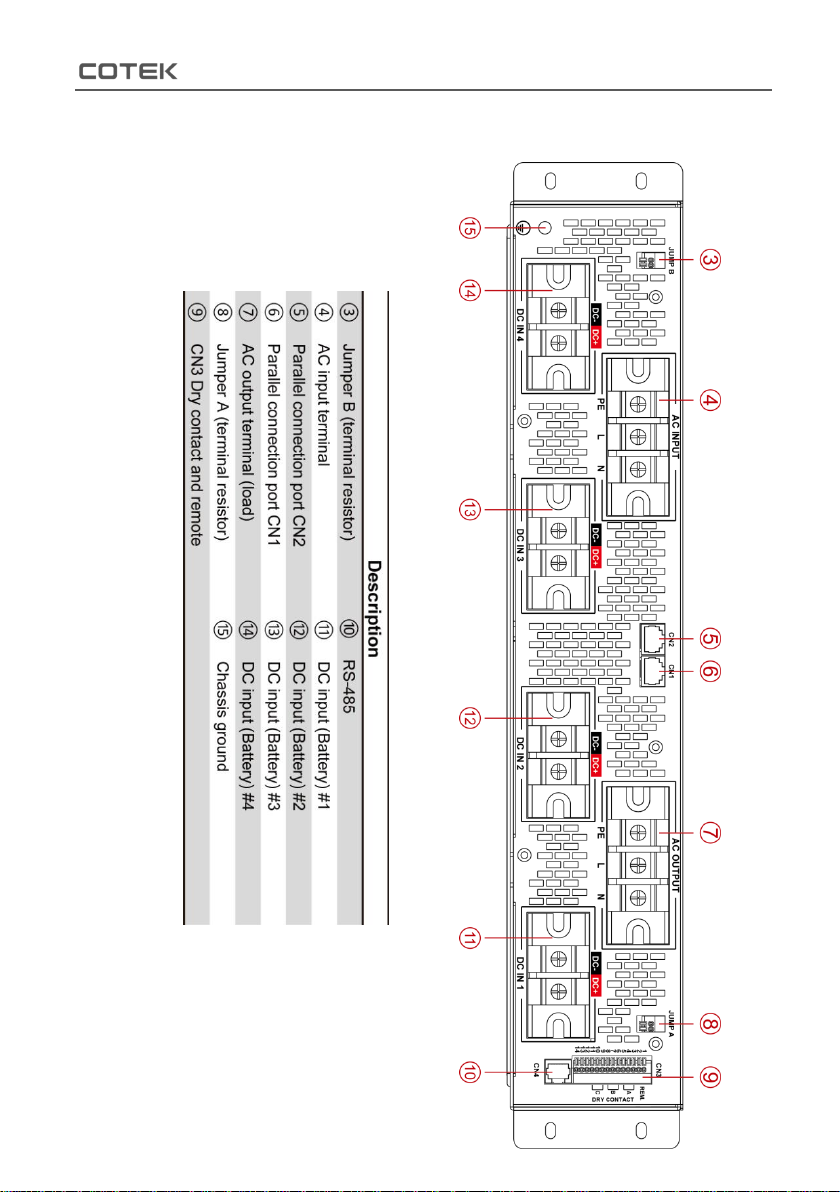
Figure 2. SR-1600 PLUS shelf rear panel
view
Table 1. SR-1600 PLUS description

3. Introduction
5
3-1. Installation
①Insert SR-1600 shelf
in to the shelf plate.
②Fix SR-1600 shelf by
4 screws at its front side.
Note: Please make sure
the mounting bracket of
your rack mount deceive
is equipped before
installing SR-1600 shelf.
Figure 3.
SR-1600 PLUS shelf installation
3-2. Green Terminal Introduction ③⑧⑨
There are three green terminals at the rear side, please refer to
following figure:
Terminal
Description
Jumper A & B
Single shelf / Parallel connection setting
CN3 Dry contact and remote
Remote setting, and dry contacts
Table 2. SR-1600 PLUS green terminal introduction

3. Introduction
6
3-2-1. Jumper A & B ③⑧
Figure 4. Jumper A & B
Pin
Function
Wiring
Status description
1
Terminal
Resistor
Pin#1 and
Pin#2
short/open
Short:
1. Signal shelf setting*Note
2. Parallel connection setting at first and last shelf
(terminal shelf)
Open:
Parallel connection:non-terminal shelf (Refer to
3-2-2.)
2
Table 3. SR-1600 PLUS jumper A & B status description
*Note:Jumper A pin1 & pin2 must be shorted and Jumper B pin1 & pin2 must
be shorted.

3. Introduction
7
3-2-2. AC Input / Output Terminal ④⑦
AC Input Terminal ④
SR-1600 PLUS provides theAC utility input terminal at the rear side,
and user can connect the AC cable at L / N / FG. The SR-1600 PLUS
support the AC input side internal parallel connection.
AC Output Terminal ⑦
The AC output terminal at the rear side of the SR-1600 PLUS. User can
connect the L / N / FG.
Figure 5. AC terminal connection
3-2-3. Dry contact and remote ⑨
Figure 6. CN3 dry contact pin assignment
Autres manuels pour SR-1600 Plus -148
1
Table des matières


