Coopra 15B Manuel utilisateur

EN
1
User instructions
(Boilers with printed circuit board type 585)
15B, 15C, 37 , 37B, 37C, 40C
Gas boiler with 3-way valve for storage cylinder…... E15B
Gas boiler for Heating …………….....……….…………….….. E15C
Combi-boiler for Heating with Hot water)............... E37
Gas boiler with 3-way valve for storage cylinder…... E37B
Gas boiler for Heating …………….....……….…………...….. E37C
Gas boiler for Heating …………….....……….…………...….. E40C
2011 585 E
Coopra Advanced Heating Technologies User instructions 15B, 15C, 37K, 37B, 37C, 40C
2
General
The appliance is not intended for use by persons with
reduced physical, sensory or mental capabilities, or lack
of experience and knowledge, unless they have been
given supervision or instruction concerning use of the
appliance by a person responsible for their safety.
Children should be supervised to ensure that they do not
play with the appliance.
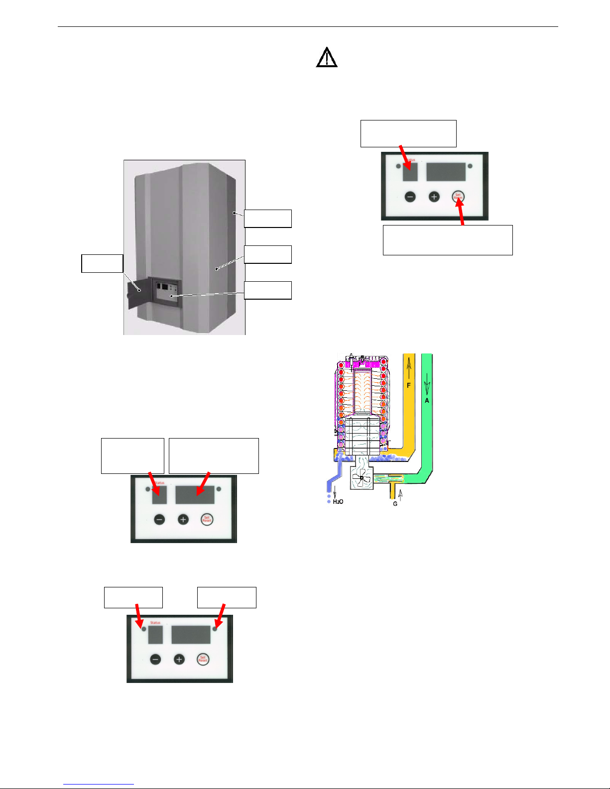
Boiler
The type plate, which specifies the type of gas for which
the boiler is factory set, is on the left hand side of the
frame.
Open the door in the cover for reading the display.
Display
LED indication
- LED is on = burner is on
- LED is off = standby (no heat demand)
- LED is flashing = unit is in lock-out
Lock-out
With malfunctions, lock-out, user may reset the boiler
using the set/reset button. However, with repeating
failures in short period of time always let your installer or
maintenance man check and repair unconditionally.
How the boiler works
The boiler is equipped with gas and combustion air
regulation controls. The purpose is to keep the gas/air
mixture in the burner as optimal as possible. This ensures
clean and reliable combustion and high efficiencies
across the entire load range of the boiler at all times, e.g.
when modulating.
A fan sucks the air
required for the
combustion through the air
feed canal (A). Because
the combustion air in the
venturi sucks an under
pressure, the correct
amount of gas (G) is
automatically added to the
combustion air.
The flammable gas/air
mixture thus obtained is
fed to the burner, via a
mixing chamber, to be
ignited at the surface of
the burner by a ceramic
glow plug. The hot
combustion gases are efficiently fed through the heat
exchanger, where they give their heat to the water. The
flue gases are fed outside, through the flue tube (F), into
a flue tube exhaust canal.
The condensation water (H2O) thus obtained is
discharged into the sewer.
Periodical maintenance
After the first year, have a recognised installer or
maintenance man inspect the unit. He can ascertain the
maintenance deadline on the basis of the inspection and
circumstances.
Cleaning the unit
Regularly clean the outside of the unit with a soft, damp
cloth. It is not necessary to shut the gas tap or switch off
the mains for this.
Never use aggressive or flammable cleaning agents.
Take note that water pipes and the flue gas exhaust can
be hot at high temperature.
F
rame
Cover
Display
Door
Value
standard, flow
temperature in
°C
Status
boiler mode,
see list
LED
not in use
unlock by pressing the
Set/Reset button briefly
Status
flashing code see list
Coopra Advanced Heating Technologies User instructions 15B, 15C, 37K, 37B, 37C, 40C
3
Tips
Depending on how much you value optimum comfort and
the lowest possible energy consumption, the following tips
can help you make optimum use of your unit:
- To help limit the energy consumption, it is recommended
to set the room thermostat to a lower temperature a few
hours before going to bed.
- Shut the radiator taps off in the rooms where you do not
want any heating.
- Turn all radiator taps fully open in the rooms that you
want to heat.
Holidays
With long-term absence, for example in the holidays, it is
recommended to leave the mains continually switched on.
The reason is to let the boiler makes a check every 24
hours.
If frost can be excluded, set the room thermostat to a low
temperature.
If frost cannot be excluded, set the room thermostat to a
temperature of 12°C or higher. The boiler is protected
with an internal frost protection. However, this does not
guarantee protection of the installation against freezing,
e.g. radiators.
Brrrr, the central heating is not working
The central heating boiler is a fairly complicated item that
is fitted with safety devices, which prevent a dangerous
situation. There can be many reasons why the central
heating is not working.
In the unlikely event that the central heating has let you
down, just when you desperately need the boiler, check
things before calling an installer for help.
Electricity
When the light of the mains switch is
on, then the boiler is connected to
the supply.
After restoration of supply power
boiler runs a de-aeration program, Status display is P.
Gas
Is the gas cock in open position?
Is there an (unusual) interruption in the gas supply?
Check by seeing whether a gas cooker in the kitchen is
working. If it is not working, call the gas company.
The gas flow can be blocked, for instance by the gas
valve strainer; then call the installer or maintenance man.
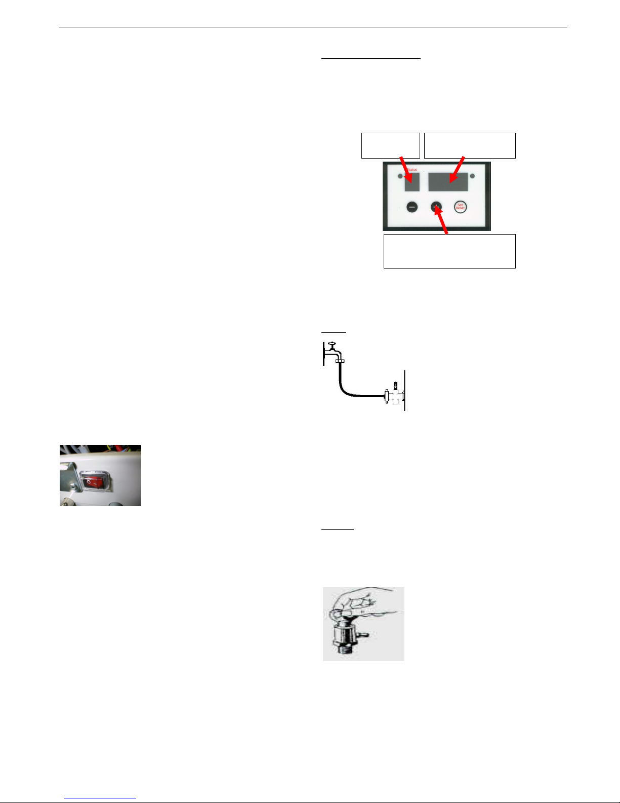
Water pressure
The user has to check the water pressure regularly and
has to top up and de-aerate the installation as necessary.
The working range of the boiler is between 0,5 and 3,5
bar. With lower and higher water pressures the burner is
blocked and the boiler gives no heat.
Water pressure reading
To read the water pressure press the (+) button for at
least 10 seconds. The Status shows P /u and the right
hand display shows the actual water pressure.
To return to normal mode, press the (-) button briefly
Automatic return is by time-out, after 3 minutes.
During operation with water pressure below 0,5 bar, the
burner is blocked. The status shows P.
Solution: Top-up with domestic water.
Filling
- Fill the system with domestic
water.
- Fully open all radiator taps.
- Connect the hose tube to the
cock of domestic water supply.
- First fill the hose tube with water
and let the air in the hose tube
escape, because you want to fill
the installation with water instead air.
- Then connect the hose tube to the filling point of the
installation, open both cocks with caution and top-up the
installation with water.
- Advised is a fill pressure between 1,5-2,0 bar.
- When the water pressure is sufficient, close the cocks
and remove the hose tube.
- After filling, the installation must be vented.
Venting
This is done with the pump(s) off. Running water can
move the air bubbles through the system constantly.
During the venting process you can switch the boiler
pump off by the boiler mains switch.
- Open radiators.
- Open the bleed cocks of the
installation one at a time. Use a
bleed cock key to do so. As soon as
water comes out of the bleed cock,
shut the cock.
- Vent the boiler, and if applicable
the hot water HWS cylinder or internal tank of
Combiboiler as well.
- After venting switch the boiler mains switch on and then
the indicating light is on.
water pressure
in bar
Status
P/u
press and hold the (+)
button for at least 10 sec.

Coopra Advanced Heating Technologies User instructions 15B, 15C, 37K, 37B, 37C, 40C
4
Indication normal operation (continuous code)
Status Description
P De-aeration program: After restoration of
supply power, both the boiler pump and 3-way
valve are switched several times with the
purpose to move eventual air out of the boiler.
The de-aeration program lasts for 2 minutes.
During de-aeration time the burner is off.
O No heat demand, stand-by
C Central heating heat demand, burner off
C. Central heating heat demand, burner on
c Central heating pump post-running
d DHW heat demand, burner off
d. DHW heat demand, burner on
b HWS heat demand, burner off
b. HWS heat demand, burner on
o Frost protection 8°C (burner off, pump running)
o. Frost protection 3°C (burner on, pump running)
C
FLASHING
Chimney sweeper function
Indication blocking mode (continuous code)
Status Description
6 Combi boiler sensor (internal tank) open
6. Combi boiler sensor (internal tank) shortcut
9 Flow or return sensor too high in temperature
A Flue gas temperature > 100°C
E No slave connected
J Central heating heat demand, anti-cycling timer
blocks burner for 3 minutes
P Water pressure too high or too low
2 Return temperature is 5°C above the flow
temperature blocks the burner.
Indication lock-out mode (flashing code)
Status Description
1 Boiler does not pass temperature test
(mostly by water problem or air bubbles)
2 Too many restarts during operation
5 Fan speed error
8 Flame detected with closed gas valve
9 Eeprom programmed
A Flue gas temperature > 100°C
(for more then 3 times within 30 minutes)
E Internal regulation fault / A/D conversion fault
E - t1 Flow sensor (open or shortcut fault)
E - t2 Return sensor (open or shortcut fault)
E - t3 Flue gas sensor (open or shortcut fault)
E Internal regulation fault / A/D conversion fault
F Too much (4) consecutive start attempts
H Flow or return sensor temperature > 105°C
Customer may use the Set/Reset button, however,
with repeating failures in short period of time always let
your installer or maintenance man check and repair
unconditionally.
Some lock-out situations can only be removed by power
restoration.
View mode
In the view mode some actual boiler values can be read.
Press the (+) button for at least 10 seconds and the view
mode will come up. The first indication is the water
pressure status P /u. On the 3 right displays read the
actual water pressure in bar.
Press the Set/Reset button once for next parameter.
When the display keys are untouched for 3 minutes, by
time-out the system will switch back to the normal status
indication.
Manual return is by pressing the (-) button once.
View mode Stand-alone boiler
Status Description
P / u actual water pressure (in bar)
] / u setpoint on flow sensor (in °C) (default)
] / u
With parameter C/r = 1 the setpoint is
switched to the return sensor or optional
system sensor.
1 / u actual flow temperature (in °C)
2 / u actual return temperature (in °C)
3 / u 0÷10V control (in Volt)
4 / u outdoor temperature (in °C)
5 / u Combi-boiler internal tank or external storage
cylinder temperature (in °C)
6 / u flue gas sensor temperature (in °C)
7 / u flame signal (in µA DC)
9 / u Last lock-out
A / u Last blocking
d / u actual system sensor temperature (in °C)
(parameter C/r=1)
Menu mode
The menu mode is for making adjustments to the boiler,
and is intended for use by installer or maintenance man.
Press the Set/Reset button for at least 10 seconds and
the menu mode will open with h=10.
Further entry is protected by a password.
Autres manuels pour 15B
1
Ce manuel convient aux modèles suivants
5
Table des matières
Autres manuels Coopra Chaudière


Manuels Chaudière populaires d'autres marques

Vaillant
Vaillant uniSTOR VIH SW GB 500 BES Manuel utilisateur

Radijator
Radijator BIO max 23.1 Manuel utilisateur

Brunner
Brunner BSV 20 Manuel utilisateur

Buderus
Buderus Logamax GB062-24 KDE H V2 Manuel utilisateur

Potterton
Potterton 50e Fiche technique

UTICA BOILERS
UTICA BOILERS TriFire Manuel utilisateur


