Communications Specialties Fiberlink 5012 Manuel utilisateur

Single Color (Black)
Single Color (Black)
on Black Background
If you need to use the CSI logo on a non-solid
background use the Photoshop Layered Files.
©2005 Spectra Vision Productions, Inc.
World Headquarters
55 Cabot Court
Hauppauge, New York 11788 USA
Tel: (631) 273-0404
Fax: (631) 273-1638
info@commspecial.com
commspecial.com
Communications Specialties’ Fiberlink® 5012 User’s Manual
Fiberlink®
5012
Universal Data Transceiver
The Fiberlink® 5012 Universal Data
Transceiver digitally transmits
RS-232/422/485 data over
multimode or single mode ber at
850 or 1310 nm. It transmits and
receives all standard data-related
signals in accordance with EIA
specications. The 5012 is suitable
for simplex, full duplex and
drop-and-repeat operation,
making it ideal for Data
Acquisition, Intelligent
Transportation, Industrial and
Manufacturing applications.

Page 2 Fiberlink® 5012 User’s Manual
Fiberlink® 5012
Contents
Welcome ........................................................................3
Features. . . . . . . . . . . . . . . . . . . . . . . . . . . . . . . . . . . . . . . . . . . . . . . . . . . . . . . . . . . . . . . . . . . . . . . . . 3
Package Contents ...............................................................3
Quick Installation ................................................................4
Technical Specications
Model Part Number Specications ............................................5
Operation Theory ...............................................................6
Installation Instructions ..........................................................7
Signal and Power Connections ...................................................8
DIP Switch Settings .............................................................10
Conguring a ring or loop data bus .............................................17
Operating Pointers .............................................................17
Troubleshooting ...............................................................19
Maintenance and Repairs .......................................................20
Warranty .......................................................................21
Accessories and Related Products ...............................................22
Contents

Page 3Fiberlink® 5012 User’s Manual
Fiberlink® 5012
Welcome
Thank you for purchasing Communications Specialties, Inc.’s Fiberlink® 5012. The 5012
transmits and receives all standard data-related signals in accordance with EIA
specications. The 5012 is suitable for simplex, full duplex and drop-and-repeat operation,
making it ideal for Data Acquisition, Intelligent Transportation, Industrial and
Manufacturing applications.
Features
• Transmits and receives all standard data-related signals in accordance with EIA
specications
• May be easily user-congured for the desired protocol, including mixed protocols
• Transmitter and receiver may be congured dierently
• Adjustment free; all digital processing and transmission
• Wide operating data rate, with low-speed mode (DC up to 2.1 mbps; 200 Kbps for
RS-232) and high-speed mode (10 Kbps - 10 mbps)
• Extended ambient operating range
• Data-derived or RTS transmit/receive switching (RS-485)
• Indicator LEDS monitor signal and power
• Card version lls one slot in 6000A card cage
• RoHS Compliant
Package Contents
• One Fiberlink® 5012
• This User’s Manual
Welcome | Features | Package Contents

Page 4 Fiberlink® 5012 User’s Manual
Fiberlink® 5012
Quick Installation Guide
The following is a quick installation guide for the 5012 model. It is intended for users familiar
with the installation of ber optic transmission systems to get “up and running” in minimal
time. Since these units are capable of being congured for operation in many dierent
modes, we strongly suggested that you consult the appropriate sections of this manual.
Optical
Connectors
For protocol and
mode selection see
User'sManual for
proper DIP switch
settings
Power
Connector
Signal
Connector
Signal Indicator
LEDs
Power Indicator
LED
5012
Quick Installation

Page 5Fiberlink® 5012 User’s Manual
Fiberlink® 5012
Technical Specications
Technical Specications
Model Part Number Specication
System Protocols* EIA RS-232, RS-422, RS-485, 2-wire or 4-wire
System Data Rate* Low speed: RS-232, DC-200 kbps,
RS-422/485, DC to 2.1 mbps
High speed: RS-422/485, 10 kbps to 10 mbps
Modes of Operation* Simplex, duplex, drop-and-repeat,
Asynchronous, RTS or
Data Derived T/R control
Operating Wavelength 850 nm or 1310 nm
Optical Connectors ST (MM) or FCPC (SM)
Operating Temperature -35 to +75 degrees C
Wavelength Loss Budget (dB) Distance (km) Loss Budget (dB) Distance (km)
Low Speed Low Speed High Speed High Speed
850 MM 0-12 0-4 0-6 0-2
1310 MM 0-14 0-14 0-8 0-8
1310 SM 0-15 0-35 0-8 0-20
* Note that as provided from the factory, the universal data transceiver is set to the RS-232 point-to-point
(200 kbps) and low speed modes of operation. In the low speed mode the unit will operate with all duty
cycles including DC (logic 0 or logic 1 continuously). In the high speed mode of operation, the system will
operate properly with all duty cycles from 50-50% to 70-30%.
General Information
The Universal Data Transceiver is fully compatible with EIA standards for RS-232, RS-422 and
RS-485 at data rates from 0 (DC) to 2.1 mbps (200 kbps for RS-232) in the low speed mode
or from 10 kbps to 10 mbps in the high speed mode. It may be used for simplex or full
duplex asynchronous transmissions in both point-to-point systems and drop-and-repeat
data networks. It may also be used as a protocol converter. Although there are no operating
controls, the user must congure the unit for the protocol, speed and mode of operation
desired.
The universal data transceiver comes in two versions, the 5012 stand-alone model and the
5018A card-cage model. The two models are fully compatible with each other.
Page 6 Fiberlink® 5012 User’s Manual
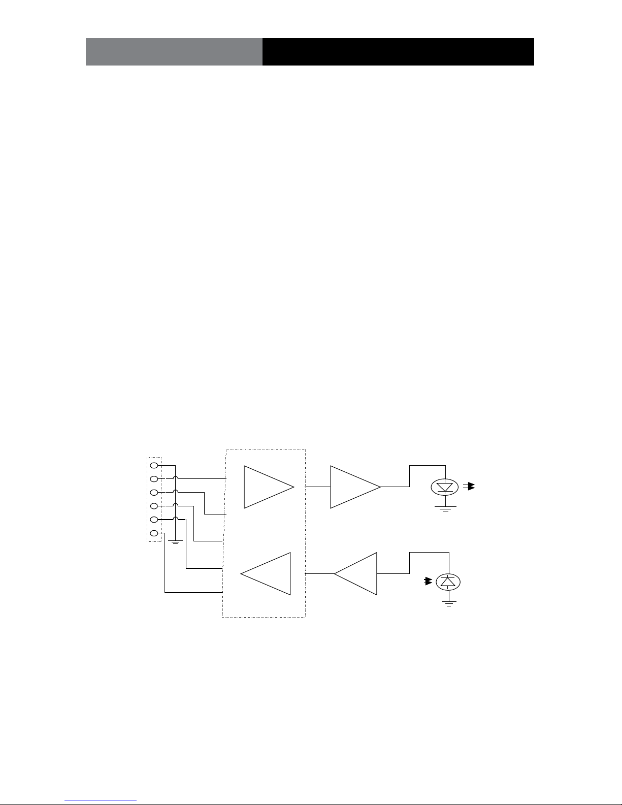
Fiberlink® 5012 Operation Theory
Theory of Operation
The transmitting section of the universal data transceiver converts an incoming RS-232,
RS-422 or RS-485 signals into pulses of light at the transmitting LED located in the “Transmit
(or Tx)” optical connector on the unit. These pulses of light equate to ON for a positive input
level and OFF for a negative or zero input level.
The receiving section of the universal data transceiver produces a user selectable RS-232,
RS-422 or RS-485 compatible output from the received light at the photodiode located in
the “Receive (or Rx)” optical connector on the unit. Due to the fact that all internal logic
signals are converted to either light-on or light-o, any protocol may be used in conjunc-
tion with any other protocol, thereby allowing the transceiver to be used as a data
converter as well as a general data transceiver. In addition, provision is incorporated to
allow drop and repeat operation with any protocol.
During normal operation, the RTS line (terminal block position 6) is not used. In external
RTS operation (for RS-485), terminal block position 6 is used as an enable input to toggle
the unit between transmit and receive. In this mode a positive input switches the unit to
the transmit mode while a zero input switches the unit to the receive mode. As an alter-
native, the unit may be automatically switched from transmit to receive by means of an
internal data-driven timer (Data-Derived T/R switching).
1
2
3
6
LED Driver
Current/Voltage
Converter
Transmit
LED
Receive
Photodiode
UNIVERSAL DATA TRANSCEIVER BLOCK DIAGRAM
Protocol Converter
4
5
Signal
Terminal Block

Page 7Fiberlink® 5012 User’s Manual
Fiberlink® 5012
Installation instructions
There are no operating controls on the universal data transceiver. Simply set the mode of
operation with the internal DIP switches and then connect the signal, power supply and
ber optic cables between the two units.
1. Connect the data processing equipment to be used to the 6 position terminal block
on the 5012 . Refer to the signal and power connections section on page 6 for specics.
Be certain that the various connections are made properly. Also be sure to only use
the positions called out for any particular protocol.
2. Set the internal DIP switches for the protocol, speed and mode of operation accord-
ing to the instructions beginning on page 8. Note: As provided from the factory, the
unit is set for RS-232, point-to-point.
3. Connect operating power ( +10 to +18 VDC ). Refer to Figure 1 for DC power
connections.
4. Connect the 5012 units together with two conductor ber optic cable. Be certain
that the “Transmit” connector of one unit is connected to the “Receive” connector of
the other unit.
5. The system should now be operational.
Installation
9-24 Volts
AC or DC
( - ) Negative
(+) Positive
The transmitting element in the Fiberlink® 5012 transmitter
unit contains a solid state Laser Diode located in the optical
connector. This device emits invisible infrared electromagnetic
radiation which can be harmful to human eyes. The radiation
from this optical connector, if viewed at close range with no
ber optic cable connected to the optical connector, may be
sucient intensity to cause instantaneous damage to the
retina of the eye. Direct viewing of this radiation should be
avoided at all times!
Figure 1:
5012 Power Connector
DC Input Polarity

Page 8 Fiberlink® 5012 User’s Manual
Fiberlink® 5012
Signal and Power Connections
The power terminal block connections for the model 5012 are as follows: +10 to +18 VDC,
position 2. DC return, position 1. Note that this input is also reverse-polarity protected.
RS-232 Signal Connections:
Description EIA Designation Terminal Positions
Chassis Ground/Common (AA) 1
Transmit Data (BA) (input) 2
Receive Data (BB) (output) 4
Signal Common (AB) 1
All other terminal block positions should not be connected for this format.
RS-422 Signal Connections:
Chassis Ground 1
Transmit Data (+) (input) 2
Transmit Data (-) (input) 3
Receive Data (+) (output) 4
Receive Data (-) (output) 5
All other terminal block positions should not be connected for this format.
The transmitting element in the “-7” single mode version of the universal data
transceiver uses a solid state Laser Diode located in the “Transmit” or “Tx”
optical connector on the unit. This device emits invisible infrared electro-
magnetic radiation which, if viewed at close range without a ber optic cable
connected to the optical connector, may be of sucient intensity to cause
instantaneous damage to the retina of the eye. As a result, direct viewing of
this radiation should be avoided at all times.
Signal and Power Connections

Page 9Fiberlink® 5012 User’s Manual
Fiberlink® 5012
RS-485 2-Wire Signal Connections:
Chassis Ground 1
Transmit/Receive Data (+) (input/output) 2
Transmit/Receive Data (-) (input/output) 3
RTS Enable (when used) (input) 6
All other terminal block positions should not be connected for this format.
RS-485 4-Wire Signal Connections:
Chassis Ground 1
Transmit Data (+) (input) 2
Transmit Data (-) (input) 3
Receive Data (+) (output) 4
Receive Data (-) (output) 5
RTS Enable (when used) (input) 6
All other terminal block positions should not be connected for this format.
When the RTS mode of operation is used, the input to terminal 6 must be “high” for the unit to transmit data
and “low” to receive data.
Modes of Operation:
On the 5012 stand-alone model of the universal data transceiver, there are two internal DIP
switches which are accessible on the bottom of the housing. These must be set to congure
the desired mode of operation.
Signal and Power Connections

Page 10 Fiberlink® 5012 User’s Manual
Fiberlink® 5012 DIP Switch Settings
Setting the MODE DIP switch
Switch setting example
For all protocols, positions 1 and 2 of the MODE DIP switch should be set as follows:
· Low speed mode (DC to 2.1 mbps):
Position 1 = ON, Position 2 = OFF
· High speed mode (10 kbps to 10 mbps):
Position 1 = OFF, Position 2 = ON
For RS-232, the data rate is limited to 200 kbps. For RS-422/485, the data rate is as above.
The universal data transceiver will not operate properly if positions 1 and 2 are both set to either ON or OFF.
12345678
O P E N
12345678
O P E N
12345678
O P E N
Switch ON
Switch O
Table des matières


