COMBA CPBBUV1-48055-UL Manuel utilisateur

©20
20
Comba Telecom. All Rights
Reserved
.
568 Gibraltar Dr., Milpitas, CA 95035| +1 866 802 7961 | www.combausa.com
1
Rev 1.11 – 01-21-2021
Comba Battery Backup Unit
CPBBUV1-48055-UL
Quick Installation Guide
Version: 1.1.2
THIS INSTALLATION GUIDE IS FOR FIRMWARE VERSION V8B01 ONLY.
FOR ALL OTHER FIRMWARE VERSIONS, PLEASE CONTACT
COMBA TECHNICAL SUPPORT FOR UPGRADE INSTRUCTIONS.
IMPORTANT! READ BELOW
UPON SYSTEM INSTALL, IF BATTERY STATUS ON WEBOMT SOFTWARE SHOWS “CUT OFF”
CHECK THE BATTERY VOLTAGE. IF ALL BATTERIES MEASURE OVER 12.5 VOLTS, RESET CUT OFF
STATUS IN MANAGEMENT TAB OF WEBOMT. IF BATTERIES MEASURE LESS THAN 12.5V, CONTACT
COMBA TECHNICAL SUPPORT FOR HELP.
COMBA TECHNICAL SUPPORT: (408) 649-2627 ext 4
Contents:
- System Diagram …………………………………………………………………… 2
- Shipping Contents …………………………………………………………………… 3
- Cable connection …………………………………………………………………… 3
- WEBOMT operations …………………………………………………………………… 6
- Firmware V8E01 Update ……………………………………………………………….. 12
- Appendix – Alarms ……………………………………………………………………. 14
- Appendix A – FW Version Control ………………………………………………………16
- Appendix B – Typical Wiring Diagrams ……………………………………………… 16

©20
20
Comba Telecom. All Rights
Reserved
.
568 Gibraltar Dr., Milpitas, CA 95035| +1 866 802 7961 | www.combausa.com
2
Rev 1.11 – 01-21-2021
System Diagram:
AC Input Breaker
Battery
Out
put Breaker
Surge Arrestor
Relay for EPO control
Charger
Controller
External Alarms
Dry Contacts
AC Input
EPO Connection
Loads
Charger Communication

©20
20
Comba Telecom. All Rights
Reserved
.
568 Gibraltar Dr., Milpitas, CA 95035| +1 866 802 7961 | www.combausa.com
3
Rev 1.11 – 01-21-2021
Battery Backup Shipping Contents:
The BBU is shipped with the following. Please check accessories to ensure all are included:
1. BBU Chassis
2. (4) 55AH Batteries
3. (3) Battery Jumper Cables
4. (8) Sets of screws/washers for 4 batteries
5. (8) Battery Terminal Caps
6. (4) Liquid Tight Connectors
Note: For Comba Annunciator, See Annunciator Panel Manual.
Before Starting
Before beginning installation, check the batteries and chassis for any shipping damage. If there are any signs of
battery acid, cracked plastic around the batteries, or other deformities, contact Comba technical support for
assistance. Note that the batteries may be shipped with an electrical grease on the battery terminals to prevent
corrosion and oxidation.
Check the voltage of the batteries before installing. All batteries should be above 12.5V when installed. If the voltage
of any battery is below 12.5V, contact Comba technical support for assistance.
Cable Connection:
1. Turn off AC Input Breaker and Battery Output Breaker
AC Input Breaker disconnects the AC supply to the Charger
Battery Output Breaker disconnects the Battery from the Load/Charger

©20
20
Comba Telecom. All Rights
Reserved
.
568 Gibraltar Dr., Milpitas, CA 95035| +1 866 802 7961 | www.combausa.com
4
Rev 1.11 – 01-21-2021
2. (Optional) Install EPO switch
If you wish to install an EPO switch: Note that the EPO connections have a preinstalled wire that
shorts the EPO+ and EPO-. Remove the preinstalled wire and connect the EPO switch; then turn
the EPO switch to its “Closed” position (Normal Status) and continue to the next step
DO NOT Set the EPO switch to “Open” (Cut Off Status)
The EPO switch can be installed at a remote location; note that the voltage-drop caused by the
wiring must be <14V
The EPO function is triggered from a relay and this relay is energized by the battery or the
charger; if the battery is over-discharged, then the EPO function may not work properly
If you do not wish to use an EPO switch, then continue to the next step directly (do not remove
the preinstalled shorting wire)
3. (Optional) Install Annunciator: See Annunciator BBU V(x) to Annunciator Panel Wiring Diagram.
4. Wire dry contact alarms and external alarms
Dry contact alarms default configurations:
ALM 1: AC Fail
ALM 2: Battery Low
ALM 3: Charger Fail
ALM 4: EXT ALM 1
ALM 5: EXT ALM 2
ALM 6: EXT ALM 3
ALM 7: EXT ALM 4
If you need to define different alarms, it can be done using the WEBOMT tool.
Note that the BBU dry contact alarms provide both Normally Open and Normally Closed configurations;
refer to the picture below for wiring instructions
Alarms from external devices (BDA, AMS, etc.) can be tied into BBU EXT ALMs so they can be
annunciated using the LEDs from the BBU front panel. In order to match the order of the BBU
Annunciator LEDs:
EXT ALM 1 shall tie to Signal Booster Fail (from BDA)
EXT ALM 2 shall tie to Antenna Malfunction (Normally from BDA)
EXT ALM 3 shall tie to System Component Failure (Normally from BDA or AMS)
EXT ALM 4 not defined

©20
20
Comba Telecom. All Rights
Reserved
.
568 Gibraltar Dr., Milpitas, CA 95035| +1 866 802 7961 | www.combausa.com
5
Rev 1.11 – 01-21-2021
By default, the EXT ALMs work with Normally Open dry contact alarm wiring; the dry contact alarm type
(Normally Open or Normally Closed) can be configured using the WEBOMT tool. The two wires from dry
contact alarms can be tied to EXT ALMs positive and negative termination block – the polarity does not
matter.
5. Install AC input wires
Primary Lead / Earthing Lead: min. 14 AWG (cable is not included)
6. Install wires for load
BBU provides 3 sets of terminations for loads
All 3 loads share the same power being supplied by the charger or batteries
Note: All Comba BDAs, MUs, RUs, and other -48V products come with a power cable.

©20
20
Comba Telecom. All Rights
Reserved
.
568 Gibraltar Dr., Milpitas, CA 95035| +1 866 802 7961 | www.combausa.com
6
Rev 1.11 – 01-21-2021
7. Install batteries, battery jumpers and connector caps
The batteries need to be installed in the straight up position as indicated in the picture (so that when the
BBU is mounted to the wall, the battery posts are on top/pointed towards the ceiling).
Partially pull out the batteries to connect all the positive terminals first, then push the batteries
back in and connect the negative terminals.
For safety, after installing the batteries always connect the black negative wire as the last step;
for battery removal, always disconnect the black negative wire as the first step.
NOTE: If provided with the unit, discard the battery support bar that was originally included in
the unit – it is no longer required to be installed.
8. Switch on both breakers; the BBU will boot up in 2-3 minutes and start working
Software Instructions:
The BBU should now be running; it will be configured to the default settings. To change the settings, or review
product identification information, you can log into the unit using the optional WEB interface (WEBOMT). After
logging in, the WEBOMT will provide the following information and options to you:
Unit information: Serial Number, Firmware versions and upgrade etc.
Unit status: alarms, charging status, temperature etc.
Customize alarming
WEBOMT Login:
Change IP address manually to 192.168.8.xxx/255.255.255.0 (DO NOT use 192.168.8.101)
Or wait for the IP address to be automatically assigned by the BBU
Use 192.168.8.101 in the browser to login
(Comba recommends using Chrome in Incognito Mode, or Firefox in private mode)
Last to connect, or
first to disconnect
when installing or
uninstalling
batteries

©20
20
Comba Telecom. All Rights
Reserved
.
568 Gibraltar Dr., Milpitas, CA 95035| +1 866 802 7961 | www.combausa.com
7
Rev 1.11 – 01-21-2021
WEBOMT interface:
Overview:
- System Status:
o Normal: the charger is operating normally
o Fault: the charger is not operating normally
In this state, the batteries may not be charging or the charger may not
be providing a consistent DC voltage to the load.
o Cut Off: the batteries are cut off from the charger
In this state, the load does not have backup from the batteries.
- Output Voltage:
o The voltage that the BBU provides to the loads
- Charging Current:
o The current draw while the BBU is charging the batteries
- Battery Status:
o Cycle charging: BBU is using high current while charging the battery
Refer to Setting page: <Cycle Charge Voltage>
o Float charging: BBU is using low current to periodically charge the battery
Refer to Setting page: <Float Charge Voltage>
o Discharging: NO AC supply; all loads are running on batteries
©20
20
Comba Telecom. All Rights
Reserved
.
568 Gibraltar Dr., Milpitas, CA 95035| +1 866 802 7961 | www.combausa.com
8
Rev 1.11 – 01-21-2021
o Cut off: Either (1) battery voltage is lower than the Cut Off Threshold so they have been cut
off from the system to ensure they can still be recharged, or (2) batteries have not properly
charged, leading to the BBU to cut them off to ensure no battery or system damage occurs.
The unit might ship with the batteries in cut off status due to no batteries connected during
factory firmware flash.
Refer to Setting page: <Cut Off TH>
o No battery: Battery is not connected
- Battery Voltage:
o The voltage of the batteries
- Alarm Status:
o Refer to Appendix - Alarm section
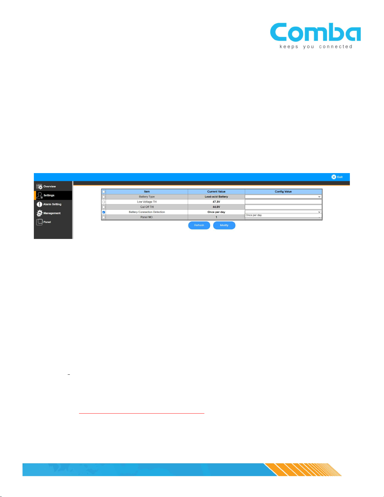
Settings:
NOTE: After setting up a new unit or upgrading the firmware, always verify that all the
parameters in this page are set to default values; always contact Comba technical support
PRIOR to changing any of the parameters
- Low Voltage TH: default = 47.3V
o Define the minimum percentage the battery capacity (e.g. 30%), and the <Battery
Low> alarm will be triggered when the remaining battery capacity reaches 30%
- Cut Off TH: default = 44V
o Battery supply to the loads will be cut off if the battery voltage is lower than the
desired threshold; the charger will try to charge the batteries when AC is restored,
but it is not guaranteed that the batteries can be charged if the batteries are over-
discharged to the point of being damaged.
- Over Temperature TH: default = 50degC
o Over temperature alarm threshold
- Battery Connection Detection: The system will check once during each 24-hour period to
verify that all batteries are connected.
- Panel NO: See Annunciator Panel Manual.
NOTE 1: IF THE BBU DOES NOT SEE A LOAD (i.e., the BDA or fiber DAS devices is powered
down, or has been removed for some reason), the Battery Connection Detection alarm may
trigger. To prevent this, we recommend disabling the Battery Connection Detection alarm
until the BDA or fiber DAS device has been powered up or has been re-installed.

©20
20
Comba Telecom. All Rights
Reserved
.
568 Gibraltar Dr., Milpitas, CA 95035| +1 866 802 7961 | www.combausa.com
9
Rev 1.11 – 01-21-2021
Alarm Setting:
- Dry Contact Alarm setting page
o Users can define an alarm or a set of alarms (to trigger a single alarm when any one
of the alarms in the “set” triggers) to trigger dry contact alarms through 1-7
o Modifying the Dry Contact Alarms will result in a pop-up menu to enable which
alarms trigger the dry contact and the ability to rename the alarm. See image below.

©20
20
Comba Telecom. All Rights
Reserved
.
568 Gibraltar Dr., Milpitas, CA 95035| +1 866 802 7961 | www.combausa.com
10
Rev 1.11 – 01-21-2021
- External Alarm setting page
o Users can define whether the external alarm is a Normally Open or Normally Closed
alarm from an external device (such as the dry contact alarms from BDA), so the
external alarms will be triggered accordingly
- Alarm Enable/Disable page
o Users can enable or disable the listed alarms
- Alarm Detect Duration
o Users can define a time interval to specify the amount of delay before an alarm is
triggered; each number set here indicates 10 seconds (e.g. 5 = 50s, 10 = 100s, etc.) –
the system will monitor the alarm status during this duration and then will trigger
the alarm after the specified delay time.
Management:
Users can obtain information and perform tasks:
- Get device S/N, temperature, Firmware version
- Upgrade firmware
o After upgrading the firmware, the user must recheck all dry contact alarm settings to verify no
changes to these have been made by the upgrade
Table des matières


