CodevDynamics AQUILA Manuel utilisateur

2022-07 v2.0
User Manual

02
4
5
7
10
11
13
16
16
17
17
21
23
23
24
26
27
28
31
33
37
48
49
51
52
56
56
57
59
62
62
63
Contents
Product Prole
Introduction
Preparing the Aircraft
Linking the Remote Controller
Aircraft Overview
Expansion Port Overview
Remote Controller Overview
Aircraft
Prole
Flight Modes
Aircraft Status Inticators
Return to Launch (RTL)
RTK Functions
Flight Recorder
Propellers
Flight Battery
Remote Controller
Prole
Preparing the Remote Controller
Remote Controller Operations
Video Transmission Descriptions
Fly Dynamics App
Manual Flight
Mission Flight
Aircraft Settings
Sensors Calibration
Radio Calibration
Application Settings
Flight
Flight Environment Requirements
Preight Checklist
Starting/Stopping the Motors
Appendix
Specications
Firmware Update
Extended Screw Holes Description
After-Sales Service Policies

03
Product Prole
This Section describes the features of
the product, guide the preparation of
the aircraft before flight, and lists the
components of the aircraft and remote
controller.

Product Prole
Introduction
AQUILA series is a quad-rotor, high-precision aerial survey drone with IP3
waterproofing. Upgrade your next mapping mission with the AQUILA – the most
compact and accurate low altitude mapping solution.
Based on the new H7 ight control system, it is compatible with PX4 and ArduPilot
dual-system open source architecture.A new dual RTK module is integrated directly
into the AQUILA, providing real-time, centimeter-level positioning data for improved
absolute accuracy on image metadata. As the same time, It has stronger anti-
magnetic interference ability and precise positioning ability.The AQUILA stores
satellite observation data to be used for Post Processed Kinematics (PPK). In
addition to optimized ight safety and precise data collection. Fit the AQUILA to any
workow, with the ability to connect this positioning system to the NTRIP (Network
Transport of RTCM via Internet Protocol) using a 4G dongle or WiFi hotspot.
CodevDynamics has rethought its drone technology from the ground-up,
revolutionizing its systems to achieve a new standardfor drone accuracy offering
customers centimeter-accurate data while requiring fewer ground control points.
Simplify workow and reduce time cost.
Users can also create customized solutions through the newly added Phalanx G1
expansion board module and customized auxiliary equipment according to business
characteristics, so that AQUILA can be closely integrated with the operation scene.
04
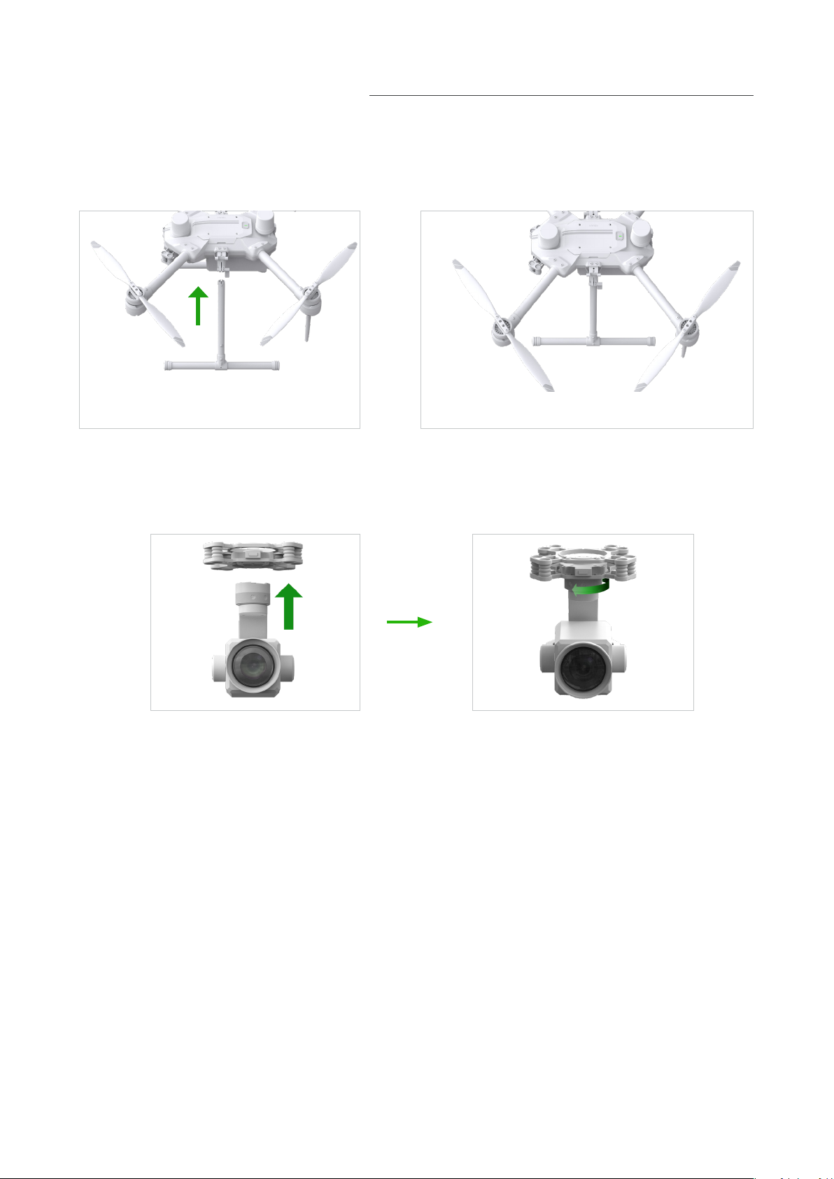
Preparing the Aircraft
1. Installing the Landing Gears
Install the landing gears,tighten the latch clockwise,and make sure it's tight.
2. Mounting the Gimbal and Camera
1. Align the white and red dots and insert the gimbal.
2. Rolate the gimbal lock to the locked position.
After installation, make sure that the gimbal lock is locked in place.
Make sure to press down the Gimbal Detachment button when rotating the gimbal
lock to remove the gimbal and camera. The gimbal lock should be fully rolated when
removing the gimbal for next installation.
05

Make sure to use included batteries, Do not use any other type of batteries.
06
4. Turning on the Aircraft
Turn on/o :
Short press the power button on the aircraft once to turn on the battery; long press
for 2 seconds to turn o the battery. The indicator light is always on after turning on
the power.
3. Battery Installation
Slide battery into the battery compartment according to the arrow's direction as
shown below.
When the upper and lower buckles on the battery are in place, a click sound indicates
the battery is securely installed. Failure to do so may aect the ight safely of your
aircraft.

Linking The Remote Controller
The aircraft and remote controller must be linked before use. Follow these steps to
link a new remote controller.
1.Turn on the remote control and enter the main interface, as shown in the figure
below, slide down the screen to start setting the binding, click to enter the App
Settings option, and select the Dlink option.
07
2.Align the tail of the aircraft to open a hole with slender hard objects like a screwd
river, reach forward to press connect button of theTransmission Module for 2 seconds
until the indicator fashes quickly.The aircraft is ready to be connected.

3.Click Tigger Bind to bind.
08
4.When conection is completed, the Transmission Module indicator will be solid and
then be o. The controller will receive data from Aircraft. Ground Status will show as
"Binded" in green.

Note:
The factory default is 5.8Ghz frequency band. If you need to switch to 2.4Ghz
frequency band, please click Enable 2.4G in Air Settings and Reboot. After the setting
is completed, switch the Groud terminal to 2.4G in the same way, the aircraft and the
remote control will be automatically bound, and the Frequency Band will be displayed
as 2.4G.
09

Aircraft Overview
1.Propellers
2.RTK Modules
3.Frame Arms
7.Motors
8.Landing Gears
4.Gimbal Detachment Button
5.Gimbal and Camera
6.Power Button
1.Binding Trigger Port
2.Battery Locker
3.Transmission Antennas
4.Flight Battery
5.Expansion Port
6.Landing Gear Latch
10
1
2
3
4
5
7
8
1
2
3
4
6
5
6
Ce manuel convient aux modèles suivants
1
Table des matières


 Manuel utilisateur")


