STARTING PROCEDURE
l. lnsert fuel coupling into fuel pump inlet adapter located above
front carrying handle.
2. Open air vent on tank. Since fuel is supplied to the carb-
uretor by means of the fuel pump, it is necessary to prime
the fuel system. The primer is located between the r.emote
tank and the fuel pump. To operate primer pump, squeeze
by hand. Upon squeezing the primer, fuel is forced into
the fuel line and carburetor. When sufficient {uel is in
the system, it becomes more difficult to squeeze the primer
This is your signal that sufficient fuel is in the system.
3. Turn throttle control twist grip to slow position.
4. Move shift handle to neutral position.
5. Turn throttle control twist grip toward high speed until
it stops. (START POSITION)
6. Pull choke knob to full "Choke" position.
7. IMPORTANT: Pull starter handle slowly until you feel
starter engage, then pull rapid motion and allow thl starter
cord to retract slowly.
6. When engine starts push choke knob in about hal{way
and.-leave in this position until engine warms up sufficient-
ly. Then push choke all the way in.
9. When ready to go.forward, turn twist grip to slow posi-
tion and pull shift lever forward.
IiITMEMBER: Do not accelerate engine to full speed until
completing "Break-In" period.
STOPPING PROCEDURE
To stop outboard turn twist grip throttle to slow position
and push stop button located on front panel. Tighten air vent
on fuel tank if outboard is not going to be run for a period
of time.
FLOODING
Flooding is usually caused by over choking the outboard.
If flooding occurs see that the choke is in "Run" position and
that the throttle twist grip is at START. Continue to pull the
starter handle until the outboard starts. It may be necessary
to remove spark plug and dry the electrodes.
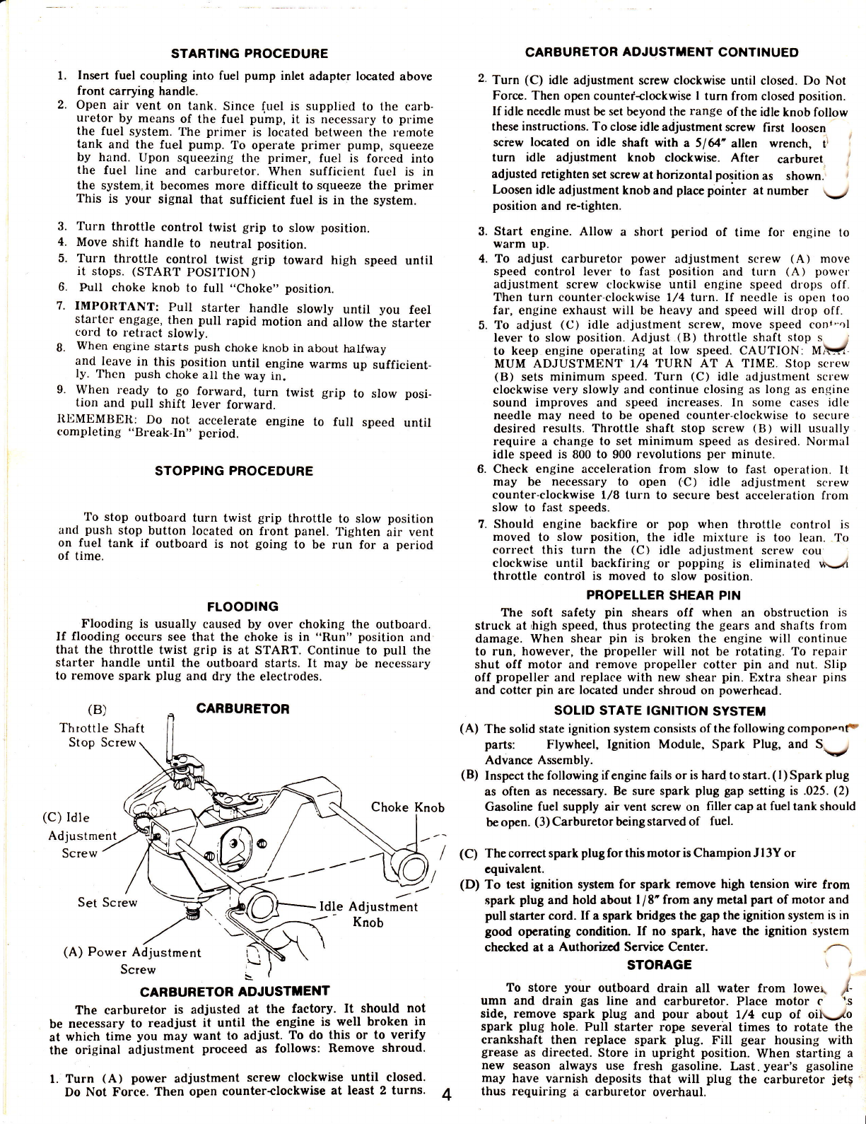
CARBURETOR
Throttle Shaft
Stop Screw
Choke Knob
(C) Idle
Adjustment
Screw -'
Set Screw Idle Adjustment
:' Knob
(A) Power Adjustment
Screw
CARBUBETOR ADJUSTTENT
The carburetor is adjusted at the factory. It should not
be necessary to readjust it until the engine is well broken in
at which time you may want to adiust. To do this or to verify
the original adjustment pnoceed as follows: Remove shroud'
l. Turn (A) power adjustment screw clockwise until closed.
Do Not Force. Then open counter+lockwise at least 2 turns.
CAREURETOR ADJUSTMENT CONTTNUED
2. Turn (C) idle adjustment screw clockwise until closed. Do Not
Forcc. Then op€n countef-clockwise I turn from closed position.
lf idle needle must be set beyond the range of the idle knob follow
these instructions. To close idle adjustment screw first loosen
screw located on idle shafi with a 5164' allen wrench, tl '
turn idle adjustment knob clockwise. After carburet. I
adjusted retighten set screw at horizontal position as shown. i
Loosen idle adjustment knob and placc poinier at number \-/
position and re-tighten.
3. Start engine. Allow a short period of time for engine to
warm up.
4. To adjust carburetor power adjustment screw (A) move
speed control lever to fast position and turn (A) power'
adjustment screw clockwise until engine speed dlops off.
Then turn counter-clockwise l,/4 turn. If needle is open loo
far, engine exhaust will be heavy and speed will drop off.
5. To adjust (C) idle adjustment screw, move speed cont-ol
lever to slow position. Adjust (B) throttle shaft stop s I
to keep engine operating at low speed. CAUTION: MVr
MUM ADJUSTMENT r/4 TURN AT A TIME. Stop screw
(B) sets minimum speed. Turn (C) idle adjustment sclew
clockwise very slowly and continue closing as long as engine
sound improves and speed increases. In some cases idle
needle may need to be opened counter-clockwise to secure
desired results. Throttle shaft stop screw (B) will usually
require a change to set minimum speed as desired. Nolmal
idle speed is 800 to 900 revolutions per minute.
6. Check engine acceleration from slow to fast operation. It
may be necessary to open (C) idle adjustment screw
counter-clockwise 1/8 turn to secure best acceleration from
slow to fast speeds.
7. Should engine backfire or pop when throttle control is
moved to slow position, the idle mixture is too lean. To
correct this turn the (C) idle adjustment screw cou'
clockwise until backfiring or popping is eliminated rx-;l
throttle control is moved to slow position.
PROPELLER SHEAR PIN
The soft safety pin shears off when an obstruction is
struck at,high speed, thus protecting the gears and shafts from
damage. When shear pin is broken the engine will continue
to run, however, the propeller will not be rotating. To repair
shut off motor and remove propeller cotter pin and nut. Slip
off propeller and replace with new shear pin. Extra shear pins
and cotter pin are located under shroud on powerhead.
SOLID STATE IGNITION SYSTEM
(A) The solid state ignition system consists of the following compononF
parts: Flywheel, Ignition Module, Spark Plug, and S. . ;
Advance Assembly.
(B) Inspect the following if engine fails or is hard to start. ( I ) Spark plug
as often as necessary. Be sure spark plug gap setting is .025. (2)
Gasoline fuel supply air vent screw on filler cap at fuel tank should
be open. (3) Carburetor bcing starved of fuel.
(C) The correct spark plug for this motor is Champion J I 3Y or
equivalent.
(D) To test ignition system for spark remove high tension wire from
spark plug and hold about I / E' from any metal part of motor and
pull starter cord. If a spark bridges thc gap the ignition system is in
good operating condition. If no spark, have the ignition system
checkcd at a Authorizcd Servicc Ccntcr.
STORAGE \ /
To store your outboard drain all water from lowel /
umn and drain gas line and carburetor. Place motor c 's
side, remove spark plug and pour about l,/4 cup of oiL.-,/o
spark plug hole. Pull starter rope sever'al times to rotate the
crankshaft then replace spark plug. Fill gear housing with
grease as directed. Store in upright position. When starting a
new season always use fresh gasoline. Last. year's gasoline
may have vArnish deposits that will plug the carburetor jetg
thus requiring a carburetor overhaul.
(B)
4