Cisco MERAKI MS390 Series Manuel utilisateur

MS390 Series Installation Guide
About this Guide
This guide provides instruction on how to install and configure your MS390 series switch. This guide also provides mounting instructions and limited
troubleshooting procedures. For more switch installation guides, refer to the switch installation guides section on our documentation website.
Product Overview
Models
Model number Description
MS390-24-HW Stackable Layer-3 24-port Gbe switch with 10G/40G modular uplinks, hot-swappable power
supplies and hot-swappable fans
MS390-24P-HW Stackable Layer-3 24-port Gbe POE+ switch with 10G/40G modular uplinks, hot-swappable power
supplies and hot-swappable fans
MS390-24U-HW Stackable Layer-3 24-port Gbe UPOE switch with 10G/40G modular uplinks, hot-swappable power
supplies and hot-swappable fans
MS390-24UX-HW Stackable Layer-3 24-port mGbe UPOE switch with 10G/40G modular uplinks, hot-swappable
power supplies and hot-swappable fans
MS390-48-HW Stackable Layer-3 48-port Gbe switch with 10G/40G modular uplinks, hot-swappable power
supplies and hot-swappable fans
MS390-48P-HW Stackable Layer-3 48-port Gbe POE+ switch with 10G/40G modular uplinks, hot-swappable power
supplies and hot-swappable fans
MS390-48U-HW Stackable Layer-3 48-port Gbe UPOE switch with 10G/40G modular uplinks, hot-swappable power
supplies and hot-swappable fans
MS390-48UX-HW Stackable Layer-3 36-port 2.5Gbe and 12-port mGbe UPOE switch with 10G/40G modular uplinks,
hot-swappable power supplies and hot-swappable fans
1

MS390-48UX2-HW Stackable Layer-3 48-port 5Gbe UPOE switch with 10G/40G modular uplinks, hot-swappable
power supplies and hot-swappable fans
Technical Specifications
•Each model has 1 dedicated management interface
•Each model has two 120G stack ports
•Each of the model has modular uplinks where you can choose from 3 different options of 10G and 40G SFP+ and QSFP+ uplink modules
•Operating temperature for each of the model: -5°C to 45°C
•Storage and Transportation Temperature: -20°C - 70°C
•Humidity: 5 to 90%
Model Interfaces PoE/ UPoE
Capabilities
Power Load (idle/max) Available PoE Hot Swap Power Supply
MS390-24-HW 24 x 1GbE R 45 n/a 79.2 / 99 W - Yes, Dual
MS390-24P-HW 24 x 1GbE R 45 PoE 84.1 / 554.4 W 445W Yes, Dual
MS390-24U-HW 24 x 1GbE R 45 UPoE 85.4 / 990.3 W 830W Yes, Dual
MS390-24UX-HW 24 x mGbE R 45 UPoE 162.7 / 809.9 W 560W Yes, Dual
MS390-48-HW 48 x 1GbE R 45 n/a 83.9 / 109.9 W - Yes, Dual
MS390-48P-HW 48 x 1GbE R 45 PoE 92.6 / 555 W 437W Yes, Dual
MS390-48U-HW 48 x 1GbE R 45 UPoE 145 / 844.9 W 822W Yes, Dual
MS390-48UX-HW 36 x 100M/1G/2.5G +
12 x 100M/1G/2.5G/5G/10G
UPoE 218.5 / 785.5 W 490W Yes, Dual
MS390-48UX2-HW 48 x 100M/1G/2.5G/5G UPoE 157.9 / 843.8 W 645W Yes, Dual
Product View and Physical Features
2

Front Panel Components
Item Component LED Status Description
1 Restore N/A Restore button to clear switch IP and local configuration settings
2 Power LED Solid amber Switch is unable to connect to the Meraki cloud or it is in the inital stage of boot-up process
Cycling through different colors Management plane is initializing and the switch initiates communication to Meraki cloud
Solid white Switch is fully operational and connected to the Meraki cloud
Flashing white Firmware upgrade in process
Off Switch does not have power
3Switch Ports Off No client connected
Solid amber 10/100 Mbps (1 Gbps on SFP+)
Solid green 1/2.5/5/10 Gbps (10 Gbps on SFP+)
3

Back Panel Components
Item Component LED Status Description
1 Management Interface Green Connected, used for easy access to the local status page
2 Stack Ports N/A Stack Cables are connected here
3 Redundant Fans Green Active and operational
4 StackPower Ports N/A StackPower cables are connected here
5 Power Supplies Green Active and functional power supplies
MS390 Series Front and Back Panel
MS390-24 Series front panel
MS390-24P Series front panel
4


In addition to the MS switch, the following are provided:
• 2 x (19 inch) Mounting brackets and screw kit that includes:
◦ 8 x Flat-head screws
◦ 4 x number-12 pan-head screws
◦ 4 x number-10 pan-head screws
◦ 1 x (4 x 20 mm) pan-head screw
◦ 1 x Ground lug screw and ring terminal
◦ 4 x Rubber mounting feet
• 1 x Default Power Supply Unit
• 3 Pre-installed Fans
• Cable guide
• Installation instruction pamphlet
• Regulatory Compliance and Safety Information handbook
Safety and Warnings
These operations are to be taken with respect to all local laws. Please take the following into consideration for safe operation:
• Power off the unit before you begin. Read the installation instructions before connecting the system to the power
source.
• Before you work on any equipment, be aware of the hazards involved with electrical circuitry and be familiar with
standard practices for preventing accidents.
• Read the mounting instructions carefully before beginning installation. Failure to use the correct hardware or to
follow the correct procedures could result in a hazardous situation to people and damage to the system.
• This product relies on the building’s installation for short-circuit (overcurrent) protection. Ensure that the protective
device is rated not greater than: 15 A, 125 Vac, or 10A, 240 Vac.
• Please only power the device with the provided power cables to ensure regulatory compliance.
MS390 Deployment Best Practices
Before powering on devices or connecting an uplink port to the LAN, ensure to follow the steps outlined below or watch this short video.
Configure your Dashboard Network
To add devices to your Meraki dashboard network please refer to the Creating a Dashboard Account and Organization document.
Check and Set Network Firmware
7

Ensure that the switch network is set to the correct firmware version. As of September 9th, 2020 MS 12.28 is the recommended version. Recommended
versions are subject to change.
You can refer to Managing Firmware Upgrades for steps to set network firmware to the desired version.
Check and Configure Upstream Firewall Settings
If a firewall is in place, it must allow outgoing connections on particular ports to particular IP addresses. The most current list of outbound ports and IP addresses
for your particular organization can be found under Help → Firewall info. The help button is located on the top right corner of any dashboard page. For more
information refer to Upstream Firewall Rules for Cloud Connectivity.
Stacking
For stacking please refer to this section Stack Cabling Installation
Assigning an IP Address
All switches must be assigned routable IP addresses. These IP addresses can be dynamically assigned via DHCP or statically assigned. MS390 switches can
support a total count of 1000 VLANs per stand-alone switch or switch stack. VLAN ID 1-1000 are configured by default, however, the active VLANs can be
changed via the local status page or dashboard. When installing an MS390, it is important to ensure that any DHCP services or IP address assignments used for
management fall within the active VLAN range.
Dynamic Assignment
When using DHCP, the DHCP server should be configured to assign a static IP address for each MAC address belonging to a Meraki switch. Other features of
the network, such as 802.1X authentication, may rely on the property that the switches have static IP addresses.
Please make sure that the DHCP server used for providing a management IP address to the switch has an available address pool that falls within the active
VLAN range.
Static Assignment
Static IPs can be assigned using the local status page on each switch. For more information on how to configure static IP from the local status page refer to this
documentation.
Static IP via DHCP Reservations
Instead of associating each Meraki switch individually to configure static IP addresses, an administrator can assign static IP addresses on the upstream DHCP
server. Through “DHCP reservations,” IP addresses are “reserved” for the MAC addresses of the Meraki switches. Please consult the documentation for the
DHCP server to configure DHCP reservations.
8

Check upstream VLAN configuration
Ensure the upstream switch/router port is configured properly and there is no VLAN mismatch.
Check STP configuration
MS390 series switches run a single instance of MST out of the box. Please refer to this document for interoperability.
Device reboot/ reset precaution
After powering on the unit or a device reboot, the power LED goes through the following cycle -
1. Solid amber
2. Cycle through different colors
3. Solid white if dashboard connectivity is successful or, remain solid amber if dashboard connectivity is unsuccessful. Different power LED colors and their
interpretation are listed under this section. It may take some time for a device to boot up so refer to the power LED indicators to understand what the switch is
doing during boot up. Be patient and let the switch complete the whole boot-up process and connect to the Meraki cloud.
Do not power down or reset the device during a firmware upgrade. A device which has its power LED blinking white is indicating that it is going through a
firmware upgrade.
Once the devices are upgraded to the latest version continue configuring other switch features/settings. For details refer to the MS documentation
Installation Instructions
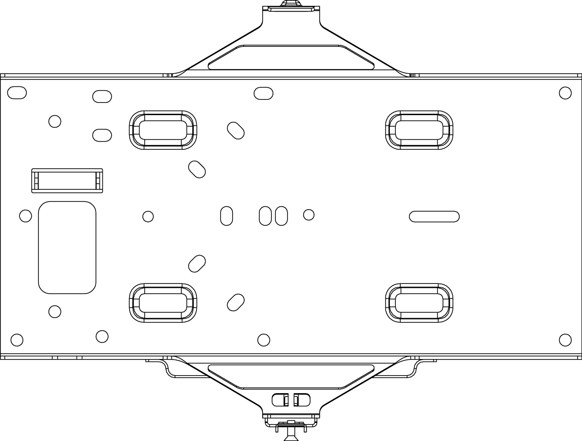
1. Attach the rack mount bracket to both sides of the switch as shown below:
Note: Each switch comes with a graphical instruction pamphlet within the box. This pamphlet contains detailed
step by step guides and images to assist in the physical install of the switch.
9

Ce manuel convient aux modèles suivants
9
Table des matières
Autres manuels Cisco MERAKI Changer

Cisco MERAKI
Cisco MERAKI MS390-24-HW Manuel utilisateur

Cisco MERAKI
Cisco MERAKI MS120-8 Series Manuel utilisateur

Cisco MERAKI
Cisco MERAKI MS250 Series Manuel utilisateur

Cisco MERAKI
Cisco MERAKI MS125 Manuel utilisateur

Cisco MERAKI
Cisco MERAKI MS450 Series Manuel utilisateur

Cisco MERAKI
Cisco MERAKI MS355 Series Manuel utilisateur


