Cirrus CRS-1XB Manuel utilisateur

PABX
Telephone Switch
User's Manual

TABLE OF CONTENTS
1. Introduction
1.1 Main Parts
1.2 Main Features
1.3 External And Internal Caller ID
2 System equipment
2.1 Classify For System Equipment
2.2 System Structure
2.2.1 Power Board
2.2.2 Audio Card
2.2.3 CO Line Card
2.2.4 Extension Card
3 Technical Index
4.1 General Programming inStructions
4.2 Input System Password
4.3 Change The Password
4.4 External (CO) Line Connection Assignment
4.5. External (CO) Line Ringing Selection
4.6 Restrict The Line's Right to Use
4.6.1 Assign Certain CO Line to Receive Calls Only
4.6.2 Asign CO Line to be Exclusively Accessed by
Authorized
4.6.3 Clear Programming of Paragraph 4.6.2
4.6.4 Assign
4.6.5 Clear Programming of Paragraph 4.6.4
4.7 Attendant Mode Assignment
4.8 Caller ID Mode Assignment
4.7.1 Operator Attendant Assignment (Default Setting)
4.7.2 Auto Attendant Assignment With
Outgoing Message(OGM)
4.7.3 Auto Attendant Assignment With
OGM For Designated CO lines
4.7.4 Record The Out Going Message (OGM)
4.7.5 Play The Out Going Message
4.7.6 Play The Music On Hold
Extension(s). For Outgoing Calls
Extension(s) to Access Only a
Designated CO Line For Outgoing Calls
4 System Programming
1
1
1
2
.........................................................................................
2
2
3
4
4
5
5
.................................................................................................
............................................................................................
...................................................................
................................................................................
.................................................................
...............................................................................
.........................................................................................
...........................................................................................
.......................................................................................
....................................................................................
6
......................................................................................
.......................................................................... 7
7
8
8
9
9
10
10
10
11
11
11
..............................................................
.............................................................................
...............................................................................
................................................
........................................................
.................................................................
......................................
........................................
...............................................
.................................................
................................................
......................................................................
.........................................
......................................................................
...............................................................
......................................................
...................................................................
........................................................................
.......................................................................
12
12
12
12
13
14
14
14

5 Operating Instruction
5.1 External Call
5.1.1 Direct External Dialling
5.1.2 Make an External Call by Dial 0
5.1.3 Outgoing by Preferred Line
5.2 Internal Call
5.2.1 Under Direct External Dialling Mode
5.2.2 Under Non-Direct External Dialling Mode
4.9 Call Restriction-Class
4.9.1
4.9.2
4.10 Restriction Group A Assignment
4.10.1 Restriction Group A Assignment Clear
4.10.2 Restriction Group B Assignment
4.10.3 Restriction Group B Assignment Clear
4.10.4 Authorized Dialling Number Assignment
4.10.5 Authorized Dialling Number Assignment Clear
4.11 Limited Call Duration of External Call
4.11.1 Limited Call Duration of Specific Extension
4.11.2 Limited Call Duration of Specific Extension Clear
4.11.3 Limited Call Duration For All Extensions
4.11.4 Limited Call Duration For All Extensions Clear
4.12
4.12.1
4.12.2
4.12.3
4.12. 4
4.13 Extension Number Assignment
4.13.1 Change Extension Number
4.13.2 Restore The Default Extension Numbers
4.14 Hook-Switch Flash Time Range Selection
4.15 System Data Default Setting
4.16 External Dialling Mode Assignment
4.16.1 External Dialling Mode Assignment
4.16.2 Direct External Dial Mode Clear
Assignment
Class Assignment For Specific Extension
Class Assignment For All Extensions
Monitor Recording Assignment
Auto Monitor Record For Specific Extension
Clear Monitor Record For All Extensions
Auto Monitor Record For Specific CO Line
Clear Monitor Recording For All CO Lines
...................................................
.....................................
...........................................
.....................................................
........................................
..............................................
........................................
.....................................
..............................
..............................................
................................
........................
.................................,,
.............................
....................................................
..............................
..................................
..................................
..................................
..................................................
..................................................
.................................
......................................
.........................................................
................................................
...........................................
.............................................
15
15
15
16
16
16
16
17
17
17
17
18
18
18
18
18
19
19
19
19
19
19
20
20
21
21
21
22
22
22
22
22
23
23
23
.................................................................
..............................................................................
............................................................
....................................................
.........................................................
...............................................................................
..............................................
..........................................

6 Maintenance & Trouble Shooting
6.1 Outgoing Calls Can`t be Made
6.2 Outside Calls Can`t Dial in
6.3 Intercom Can`t be Made
7 Appendix
7.1 PC Bill Charging System Instruction
7.1.1 PC Bill Charging System Installation
7.1.2 System Setting
7.1.3 CO Line Monitor (Outward / Incoming)
7.1.4 Extension Monitor
7.1.5 Charging Parameters Setting
7.1.6 Host Setting
8 Warranty
5.3 Receiving an External Call From The CO Line
5.3.1 Operator Attendant Mode
5.3.2 Auto-Attendant Mode
5.4 Call Pick up
5.5 Transfer an External Call to Another Extension
5.6 Internal Call Transfer ( EXT. to EXT. )
5.7 Party Conference ( Between 2 EXTs. And 1 CO Line)
5.8 Make an External Call With Help of
Operator or Assistant
5.9 Priority Access
5.10 Call Forwarding
5.11 CO Line Appointment
5.12 Paging
5.12.1 Extension Group Assignment
5.12.2 Listen Broadcasting by Extension
5.12.3 Extension Broadcasting (Conference)
5.12.4 Outside Caller Look For Somebody
by Broadcast
5.13 Self-Detect of Ringing And Extension Number
....................................
........................................................
..............................................................
..............................................................................
...................................
............................................
............................
..............................................................
.........................................................................
......................................................................
..................................................................
.................................................................................
.................................................
............................................
........................................
........................................................................
..................................
23
23
24
24
24
25
26
26
27
27
27
28
28
29
29
29
29
..............................................
.......................................................
.........................................................
..............................................................
30
30
31
31
.................................................................................
................................................
..........................................
....................................................................
........................................
................................................................
..................................................
........................................................................
32
32
32
32
33
33
34
34
................................................................................... 35

-01-
This PABX is designed to provide a low cost professional telephone switching system.
Up to 8 external telephone lines and up to 128 internal extensions can be connected.
1.1 MAIN PARTS
Base (CPU) Board: Has row sockets, CPU and some elements..
Power Supply Card: It is connect with base (CPU) board by soft wire, adopt the high-
frequency switch transformer can supply the stable voltage from 88V to 260V, adapt
the power of different countries. In case of power failure, you can connect external
battery to keep the unit working.
Audio Card: There are have Audio Input / Output ports, Monitor port and PC port.
CO Line Card: Have 8 CO line ports in each CO line card with the contra-polar detect
function and 3kv arresters protection.
Extension Card: Have 8 Extension ports in each Extension line card, use RJ11 socket.
1.2 MAIN FEATURES
Operator Attendant Mode -- allows an operator or one designated extension to
answer all incoming calls.
Auto-Attendant Mode -- allows the external caller to dial the desired extension or
operator directly according guide of OGM (Out Going Message).
Call Transfer-- allows the extension to transfer an external call to another extension.
Call Pick Up -- allows a non ringing extension to answer a call to another extension.
Music on Hold with Internal or External Source Option.
External CO Line Ringing Assignment -- any extension(s) can be assigned to ring,
when there is an external call.
Change Extension Number -- any extension can be allocated any extension number
in the rang from 100 to 999.
Call Restriction -- controls what numbers an extension can dial.
3 Parties Conference -- 2 extensions can speak to an external caller at the same time.
Internal Call -- call from one extension to another ( free of charge)
15 Communication Paths
Call Forwarding -- user can program their extension to forward an external or internal
call to another telephone extension.
External Audio Input & Output -- The user can Input or Output the broadcast or other
external Audio sources.
CO Line Appointment -- the system will notice the extension user automatically once
there is has free CO line.
Voice Recorder (optional)
Computer with Call Accounting Package (optional)
1. INTRODUCTION

-02-
System Equipment include the PABX main parts and outer equipments such as Battery,
Voice Recorder and Computer etc. The equipments are as below figure:
2 SYSTEM EQUIPMENT
2.1 CLASSIFY FOR SYSTEM EQUIPMENT
EXTERNAL LINES = 8 INTERNAL LINES = 128
8128 Structure
Power supply box
Tone board
01-08 C.O
line board
Empty socket
Extension board
Extension board
Extension board
No.1
Extension board
01 02 03 04 05 06 15 16 17 18 19 20
Extension
Computer Recorder
Audio amplifier
Loudspeaker
Microphone
Radio
Reserve Battery
Power supple
Line frame
C.O line C.O line
1.3 EXTERNAL AND INTERNAL CALLER ID
This PABX is capable of receiving external FSK or DTMF Caller ID send from the
local telephone company. In order for the Caller ID to work, the user must subscribe
to the Local Telephone Company for the service.
Internal Caller ID is available within all of internal extensions.
External Calls with telephone number of caller transferred to the internal extensions
telephone. The internal extension telephone must have DTMF Caller ID detection
capabilities. If the external call is transferred to another internal extension, the
Caller ID will be transferred to the new extension too.
-03-
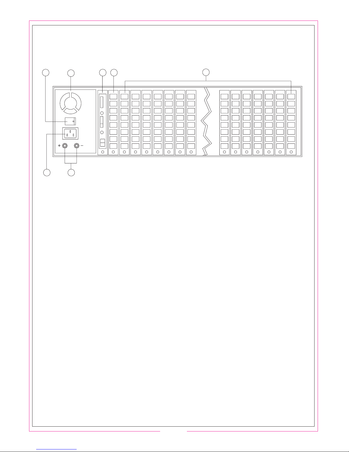
2.2 SYSTEM STRUCTURE
6
15
2
34
7
PART NAME:
1. Ventilate hole for heat dissipating
2. Power switch
3. Power sockets
4. Connected pole for external battery, the left is positive and the right is negative.
5. Audio Card
6. CO line card port 1 to port 8
7. Extension card
POINTS OF ATTENTION WHEN CONNECTING:
Be sure the power is OFF before installation, pull out the cards straightly, please insert
the cards and screw on. The system can automatic detect equipment, you could change
the cards freely, the system can work normally even if you don't insert Extension Cards
by order.
Please reconnect with power after finish installation, make sure the indicate light work
normally, if has any abnormity, you should disconnect the power supply to check again.

-04-
Generater mode
of dialing tone,
echo tone, busy tone
Tone/signal processor
Generator of
tone and music
Record/play
control
DTMF
Encoder
External music input
Volume Switch
Audio Input
Audio output
Fans for dissipate heat
Power switch
Power sockets
Wiring terminal
for storage battery
12V 12V 12V 12V
48V
The Power Board is adopt high frequency power
switch with power range is between 88V to 260V.
In case of power failure or the local voltage lower
than 88V, the back-up battery can offer the power
to keep the unit working normally.
The battery is charged automatically after power
is restore to ensure the communication continues.
The system can work at least 7 hours when power
failure by using 7A reserve battery; if adopt 12A
battery it can work at least 12 hours, such analogy.
Voltage of battery is 48V, it can up to 50V after full
charge. Normally, the battery is 12V each unit, you
can connect with FOUR batteries (see right diagram)
Be sure the connection of battery is correct to avoid
PABX or battery is damaged.
2.2.2 AUDIO CARD
The Audio Card is take charge to generate various
of signal tone, i.g.Dial tone, Ringing tone,Busy tone,
Verify tone and OGM, etc.
It also charges some accessorial functions.
i.g. PC network,Voice Recording, paging,
Audio Input / Output.
.
Monitor Record Input
2.2.1 POWER BOARD
PC COM port
Record
Paging
-05-
C.O line
connection control
C.O Line
thunder bolt
device
Stable voltage
C.O line
polor checking
C.O line
ringing checking
(Arrange CO Line number from bottom to top)
CO Line Port
CO Line Port
8#
7#
6#
5#
4#
3#
2#
1#
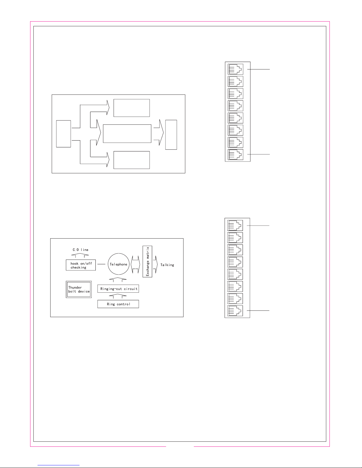
2.2.3 CO LINE CARD
The CO line card is take charge to Ringing Detect,
Control-polor Detecting, Arresters, Audio Amplifying,
CO line ON/OFF,etc.
2.2.4 EXTENSION CARD
Extension card is the main part of unit.
It have hook-switch ON / OFF detecting,
Ringing Control,ringing-cut circuits and talking matrix.
The user need only add or reduce the CO line or Ext.line card
to increase or decrease the capacity, suggest install expansion
cards by order from LEFT to RIGHT to keep continuity of the
default numbers.
You must to OFF the power supply when add or reduce the
expansion cards to avoid the unit can't work normally.
(Arrange Ext.Line number from bottom to top)
Ext.Line Port
Ext.Line port
8#
7#
6#
5#
4#
3#
2#
1#

-06-
Capacity: CO Lines = 8
Extensions = 8 to 128
Exterior sockets: Extension / C.O line Port, PC network Port, Audio Input/ Output Port,
External Music Port, Voice Recorder Port, Broadcast Port
Communication Channels: 15
Transmission Attributes: Extension to Extension 1.5dB;
Extension to Trunk line 2.0dB;
Ringing Current = 65V/50Hz;
Feeding Curren = 48V-60V/25mA;
Relative Unbalance Against Ground: 300Hz-600Hz 40dB;
600Hz-3400Hz 46dB;
Dialing Mode: DTMF
Receiving Frequency:
Signal Tone:
CO Line: Tone from Local Telephone Company;
Internal Dialing Tone: 450Hz, Continuous Square Wave;
Internal Ringing Tone: 450Hz, square wave, 1 second on and 4 seconds off;
Internal Busy Tone: 450Hz, square wave, 0.3 second on, 0.3 second off;
Internal Verify Tone: 450Hz, square wave, 1 second on;
Internal Error Tone: 450Hz, square wave, 0.3 second on, 0.3 second off ;
Power Supply: AC220V 10% Limited Range = 88~260V
Power consumption: 50VA
Audio Input Voltage level = 1 Vrms Impedance =10K
Audio Output Voltage level = 200 Vrms Impedance = 1K
Voltage of Back-up Battery = 48V
Charge Current 100mA
Voltage of Voice Recorder Control: 48V/10V
In Point Environment: Temperature: 32F-104F(0 C-40 C);
Relative humidity 90%
3 TECHNICAL INDEX
Table des matières


