then press center button of the k
automatic or manual end stop c
Start Motor Calibration remo
Spreading is done by pressing one of the user keys .. 4. Spreading function needs to be assigned to the desired user keys*. Default
is*: U -4 spread the wheel scale. So there are four different spreading setups available.
To set a spreading:
a) Move wheel to the desired first starting point, press a user key for more than second and keep pressing during the procedure
b) Respective yellow LED starts flashing
c) Move wheel to the desired second point, release the user key
d) Spreading is applied between the two points, respective yellow LED lights up continuously
To switch off a spreading: Press the user keys for which a spreading is activated less than second, respective yellow LED goes off.
To recall a formerly programmed spreading: Press the same user key again for less than second.
*Currently the assignment of spreading function is fixed to the default set up. Later software versions will allow to assign
Unlike commonly used lenses in the film industry the lenses for still cameras do not feature physical end stops on their
not possible to calibrate so-called photo lenses by the motor controller automatically.
The MagNum motor controller addresses this issue by
allowing a desired motor socket to be configured as "Lens Type = photo". The manual procedure is as follows:
mount motor as normal on the support rod and engage it to the lens in a middle position of the available range of movement
press calibration button once; motor LEDs start flashing fast but motor will not start moving on its own as it would in "Cine" mode
move motor by hand by manually turning lens to both of the limits (infinite & near) of the lens gear
turn motor back to a middle position after
press calibration button a second time , motors will now start moving measuring automatically lens parameters between the two
end points
after this calibration is finished
Hints:
As most motors show a certain amount of play/backlash, turn the motor a little further than normally necessary in order to compensate
play regarding the correct end stops on both limits.
Some motors do not allow turning manually in both directions – in this case engage the motor on one limit and turn
direction to the opposite limit.
operate reversed. Operation d
depends on how motors are mounted
and on the preferences of the user
*Setting is stored in the hand u
is independent from settin
Switch the hand unit ID to 2 if
two controllers shall be used (s
functions F & I to two controllers). ID
controls F & I by default. If a second
unit is set to ID 2, this unit wi
trol of motor I by its hand
used.
You must not have more than
hand unit set to the same ID!
Left-Handed: If "yes",
rotated by 80° in order to make left-
handed operation more easy
Wheel/Slider Cal.
Set Up Hand Unit
Select, whether several displays shall appear on
the main screens info area (i.e. Cam.-Power)
Wheel/Slider Cal.: Basic calibration of the hand wheel to its
respective mechanical operating range
Iris)
Mode: Switch to dimmer m
Dimmer cable can be controlled.
Range: Switch to 3D Rig mode
required
Direction : Reverse motor direction
Play/Safety: Modify play (b
compensation for heavily used m
fety distance, the motor stays away from the
mechanical Lens End Stops (S3D Rigs). Torque:
the motor to mid (50%) or low (25%).
Lens Type:
Cine = End stops will be calibrated automatically; Photo
= End stops are calibrated manually.
*Setting is stored in the motor box in the non-
editable on hand unit 2 as well
Save Exit Cancel
Direction
Range
Play/ Safety
2 can trigger the record signal
Select mode entry and modify t
mode with -/+ buttons
*Setting is stored in the motor b
the non volatile memory and
editable on hand unit 2 as well
Set Up the Record Start/Stop Trigger*
Light ON/OFF
Radio Channel
Record Trigger
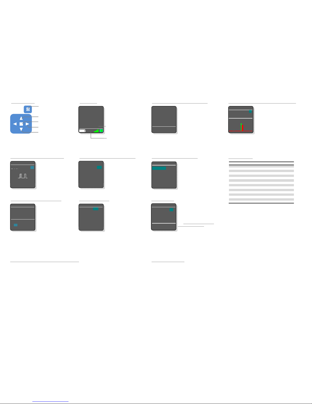
(press Center Button from Main Screen)
Select radio channel and range
ect camera record start/stop mode
Reverse wheel &/or slider operating
Start motor calibration remotely
Motor setup (torque ; direction;
Select hand Unit ID, serial socket
mode, calibrate the hand wheel &
seconds to switch hand unit off;
be used to exit a sub menu as well
Select menu item (up)
Press center button to enter set up
menus
Edit values (left = -; right = +)
Battery indicator
Hand unit ID (can be or 2)
RF signal strength indicator
Bidirec
Display of power supply voltage on
*Display can be disabled/enabled on menu entry "Display Options"
the motor output
Motor 2: No support
with MN- 00 motor controller!
Servo Lens Setup*: No Support
red in the motor box in the non
te: When this screen is visible
connection is temporarily disconnected as the hand unit scans
through all available RF channels at this time searching for
possible frequencies. For GHz range (Channels 5 - F) internal
antennas are used.
Set the Frequency Range and the Radio Channel


