ChlorKing NEXGEN10 Manuel utilisateur

NEXGEN10 Installation REV2 Page 1 of 41 04/11/2019
NEXGEN10 and 10R
Installation, Operation, and
Maintenance Manual

NEXGEN10 Installation REV2 Page 2 of 41 04/11/2019
TABLE OF CONTENTS
1.0 DESCRIPTION 3
1.1 General Information 3
1.2 Principals of Operation 4
1.3 Specifications, Certifications, and Sizing Guidelines 5
2.0 INSTALLATION 7
2.1 Unpacking 7
2.2 Storage 7
2.3 Safety Considerations 7
2.4 Plan Ahead 9
2.5 Additional Parts Required for Installation 9
2.6 Power Supply Electrical Connections 10
2.7 Bonding 11
2.8 Plumbing Connections 12
2.9 Saturated Salt Feeder Installation 14
2.10 Plumbing the Overflow 15
2.11 Preparing the pH Neutral System 16
2.12 Plumbing the Hydrogen Vent 16
3.0 OPERATION 17
3.1 Start-up Procedures and Checks 17
3.2 Adjusting Chlorine Output 17
3.3 Touch-screen Icon Explanations 18
3.4 Using the Touch-screen 19
4.0 MAINTENANCE 26
4.1 Routine Maintenance 26
4.2 Cell Cleaning Procedure 26
5.0 WARRANTY INFORMATION 41
Note: This manual is subject to change at any time based on system improvements,
design changes, authorized modifications or new information. Please consult ChlorKing
for the latest revision.
Manufacturer:
ChlorKing Inc
2935 Northeast Parkway
Atlanta, GA 30360
1-800-536-8180
NEXGEN10 Installation REV2 Page 3 of 41 04/11/2019
SECTION 1
DESCRIPTION
1.1 GENERAL INFORMATION
The NEXGEN system is an on-site sodium hypochlorite generator designed for
commercial swimming pool applications. The NEXGEN is capable of producing up to 12
pounds of equivalent chlorine per day. The system manufactures bleach continuously
from a salt concentration of 5000ppm to 7000ppm and uses the water from the pool as a
raw material. This unique feature eliminates issues with high TDS levels and requires
less salt as raw material than traditional methods. The NEXGEN is designed for
commercial service and can be run 24 hours a day or controlled by any pool controller.
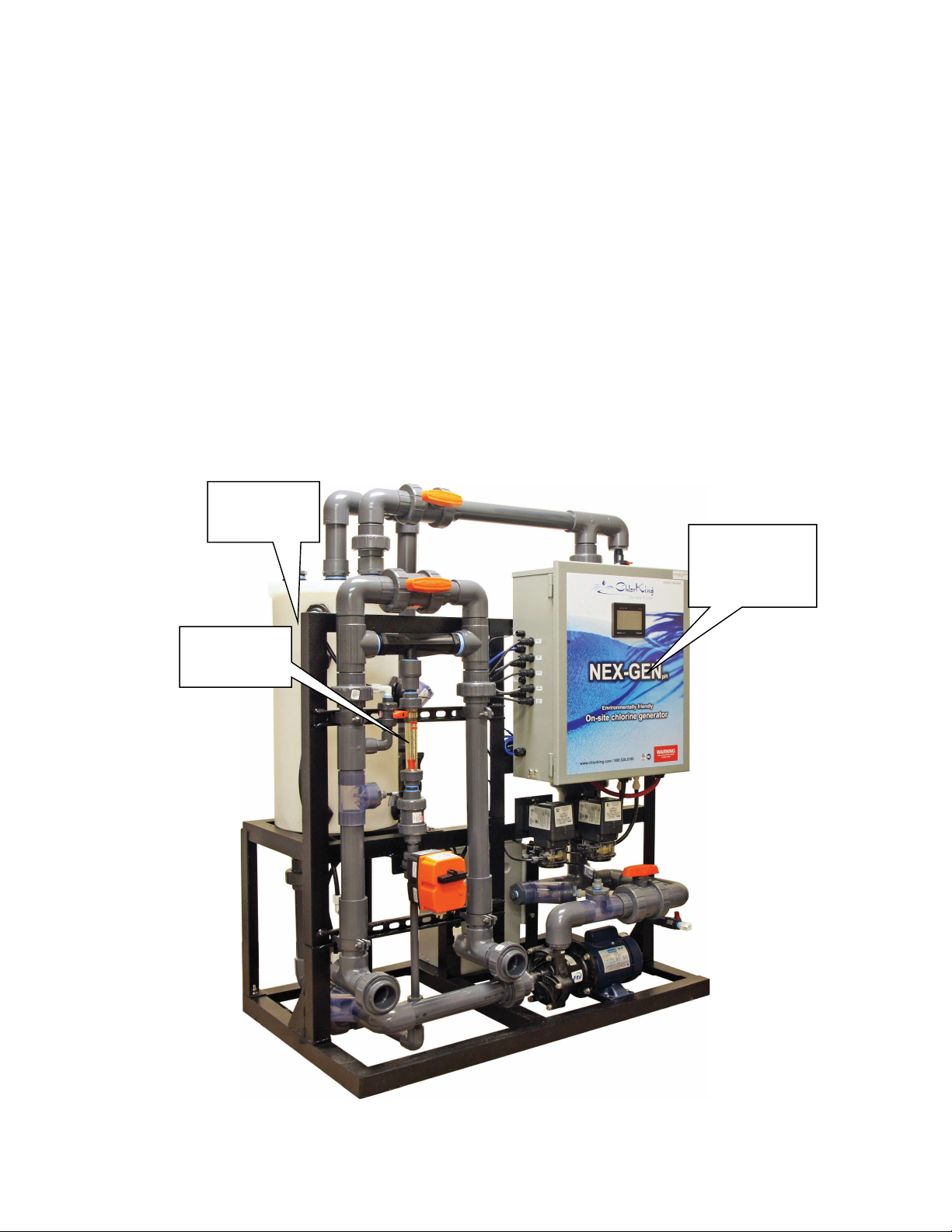
“R” models are reverse polarity which reduces maintenance. The basic components of
the NEXGEN are outlined below.
Production
Tank
Chemical
Metering
Power
Supply and
Control Box

NEXGEN10 Installation REV2 Page 4 of 41 04/11/2019
1.2 PRINCIPALS OF OPERATION
Production Tank Assembly
The production tank assembly consists of a polyethylene tank, an external electrolytic
cell, a circulation pump, and heat exchanger. Pool water from the pool return line is fed
into the production tank. The circulation pump circulates water through the electrolytic
cells and heat exchanger. The water in the tank is maintained between 5000-ppm and
7000-ppm salt concentration. The electrolytic cells produce a 1666-ppm to 2500-ppm
sodium hypochlorite solution. The sodium hypochlorite flows to the pool at flow rates from
.16-gpm to .6-gpm. The flow rate through the tank dictate the amount of sodium
hypochlorite produced. Sodium hypochlorite can be produced up to 12lbs of equivalent
chlorine. The sodium hypochlorite flows to the pool for use in disinfection. The heat
exchanger has fresh pool water pumped through the coils to maintain tank temperatures
of no more than 10 degrees F above the pool water.
Dilution Fan
Electrochemical production of sodium hypochlorite produces hydrogen as a byproduct.
The dilution fan pumps fresh air into the production tank to dilute the hydrogen and force
it out the vent. The vent must be vented to outside atmosphere.
Saturated Salt Feeder
The saturated salt feeder supplies the production tank with a constant supply of salt to
produce sodium hypochlorite. Salt is used at the rate of 2 pounds per pound of equivalent
chlorine produced or 3 pounds per pound of equivalent chlorine produced depending on
production quantity selected. The saturated salt feeder is filled manually. Salt is pumped
using standard peristaltic chemical feed pumps.
Chemical Metering
Chemical metering is accomplished using a venturi. The flow through the venturi is
adjusted to provide the flow rate necessary to deliver the rated production of chlorine to
the pool.
Power Supply and Control Box
The power supply provides the current to the electrolytic cells to produce the rated amount
of sodium hypochlorite. The power supply houses all the safety features to prevent
system operation in the event of a malfunction.

NEXGEN10 Installation REV2 Page 5 of 41 04/11/2019
1.3 GENERAL SPECIFICATIONS
Sodium hypochlorite production:
NEXGEN10 - Up to 12 pounds per day at 7000ppm
NEXGEN10R - Up to 12 pounds per day at 7000ppm
Maximum pool return line pressure:
25 PSI including plumbing to and from the venturi injector
Electrical requirements:
NEXGEN10 and 10R
Rated 208/240 VAC, 22.38 A, 50/60 Hz.
Requires:
208/240 volt single phase connection @ 30 amps and 50/60 Hz
120 volt connection to a chemical feed controller or 120 volt outlet @1 amp
Certifications
NEXGEN10 and 10R are certified for indoor installation.
NSF Standard 50
UL Standard 1081
CSA Standard C22.2 #218.1
PRMA Reg. No. 33004
Sizing guidelines
Chlorinator sizing must comply with local codes. Please contact your local health
department for specific requirements or contact your local ChlorKing representative for
assistance.

NEXGEN10 Installation REV2 Page 6 of 41 04/11/2019
DIMENSIONS
31.0
18.0
6.0
18.0
20.0 20.0
44.0
30 Gallon
Tank
30 Gallon
Tank

NEXGEN10 Installation REV2 Page 7 of 41 04/11/2019
SECTION 2
INSTALLATION
2.1 UNPACKING
Units are shipped from the factory. In the event of damages during shipping, it is the
responsibility of the customer to notify the carrier immediately and to file a damage claim.
Open the crate carefully and examine all material inside.
2.2 STORAGE
When storing units, use the original packaging and store under a shelter to protect the
contents from weather.
2.3 SAFETY CONSIDERATIONS
IMPORTANT SAFETY INSTRUCTIONS
READ AND FOLLOW ALL INSTRUCTIONS
SAVE THESE INSTRUCTIONS
WHEN INSTALLING, OPERATING, AND MAINTAINING THIS EQUIPMENT, KEEP
SAFETY CONSIDERATIONS FOREMOST. USE PROPER TOOLS, PROTECTIVE
CLOTHING, AND EYE PROTECTION WHEN WORKING ON OR INSTALLING THE
EQUIPMENT. FOLLOW THE INSTRUCTIONS IN THIS MANUAL AND TAKE ANY
ADDITIONAL SAFETY MEASURES APPROPRIATE. BE EXTREMELY CAREFUL IN
THE PRESENCE OF HAZARDOUS SUBSTANCES.
THE PERSONNEL RESPONSIBLE FOR INSTALLATION, OPERATION, AND
MAINTENANCE OF THIS EQUIPMENT MUST BE FULLY FAMILIAR WITH THE
CONTENTS OF THIS MANUAL.
ANY SERVICING OF THIS EQUIPMENT MUST BE DONE WITH THE UNIT FULLY OFF
AND DISCONNECTED FROM THE POWER SOURCE AND ALL PRESSURE BLED
FROM THE LIQUID LINES.
WARNING
CHLORKING® SYSTEMS ARE INTENDED TO BE INSTALLED ACCORDING
TO ALL LOCAL AND NATIONAL REGULATIONS.
CONNECT THE EQUIPMENT ASSEMBLY TO A CIRCUIT PROTECTED BY A
GROUND-FAULT CIRCUIT-INTERRUPTER.

NEXGEN10 Installation REV2 Page 8 of 41 04/11/2019
ONLY A CERTIFIED TECHNICIAN MAY INSTALL AND SERVICE THE
CHLORKING® NEXGEN SYSTEM.
MODIFYING THE CHLORKING® NEXGEN SYSTEM IN ANY WAY MAY CAUSE
BODILY INJURY AND WILL VOID THE WARRANTY.
DO NOT ALLOW CHILDREN OR ANYONE NOT CAPABLE TO OPERATE THE
CHLORKING® NEXGEN SYSTEM.
ONLY REPLACE COMPONENTS WITH THOSE SPECIFIED BY THE
MANUFACTURER.
WHEN INSTALLING THE SYSTEM, ENSURE THAT POWER IS LINKED TO
THE MAIN PUMP POWER SOURCE FOR THE POOL TO ENSURE THAT THE
CHLORKING® NEXGEN SYSTEM NEVER OPERATES WHEN THE PUMPS
ARE OFF.
ALL BOXES ON THE CHLORKING® NEXGEN SYSTEM CONTAIN HIGH
VOLTAGE COMPONENTS. NEVER OPEN ANY BOX WHILE THE POWER IS
ON.
THE SYSTEM HAS THE POTENTIAL TO RELEASE HIGH DOSES OF
CHORINE. USE CAUTION WHEN HANDLING, SERVICING, OR OPERATING
THE EQUIPMENT.
DO NOT ENERGIZE OR OPERATE THE SYSTEM IF THE CELL HOUSING IS
DAMAGED OR IMPROPERLY ASSEMBLED.
THE MOUNTING LOCATION OF THE UNIT MUST BE AT LEAST 1.5 METERS
FROM THE POOL.
CONSERVEZ CES INSTRUCTIONS
LORS DE L'INSTALLATION, DE FONCTIONNEMENT ET L'ENTRETIEN DE CET
ÉQUIPEMENT, GARDEZ LES CONSIDÉRATIONS SUR LA SÉCURITÉ AVANT
TOUT. UTILISER DES OUTILS APPROPRIÉS, DES VÊTEMENTS DE PROTECTION
ET LUNETTES DE PROTECTION LORSQU'ILS TRAVAILLENT SUR OU À
L'INSTALLATION. SUIVEZ LES INSTRUCTIONS DE CE MANUEL ET PREND LES
MESURES DE SÉCURITÉ SUPPLÉMENTAIRES APPROPRIÉES. SOYEZ
VIGILANTS EN PRÉSENCE DE SUBSTANCES DANGEREUSES.
LE PERSONNEL CHARGÉ DE L'INSTALLATION, DE FONCTIONNEMENT ET
D'ENTRETIEN DE CE MATÉRIEL DOIT ÊTRE PARFAITEMENT FAMILIARISÉ AVEC
LE CONTENU DE CE MANUEL.
AUCUNE OPÉRATION DE MAINTENANCE DE CET ÉQUIPEMENT DOIT ÊTRE
FAITE AVEC L'UNITÉ ENTIÈREMENT ÉTEINT ET DÉBRANCHÉE DE
L'ÉLECTRICITÉ ET TOUTE LA PRESSION SAIGNÉ À PARTIR DES LIGNES DE
LIQUIDES.
MISE EN GARDE

NEXGEN10 Installation REV2 Page 9 of 41 04/11/2019
CHLORKING ® SYSTEMES SONT DESTINES A ETRE INSTALLES SELON
TOUS LES REGLEMENTS LOCAUX ET NATIONAUX.
CONNECTER LE MONTAGE DE L'ÉQUIPEMENT SUR UN CIRCUIT
PROTÉGÉ PAR UN DISJONCTEUR DE FUITE À LA TERRE.
SEUL UN TECHNICIEN CERTIFIE PEUT INSTALLER ET ENTRETENIR LE
SYSTEME CHLORKING ® NEXGEN.
MODIFIANT LA CHLORKING ® NEXGEN SYSTEME EN QUELQUE SORTE
PEUT CAUSER DES LESIONS CORPORELLES ET LA GARANTIE
ANNULATION.
N'AUTORISENT PAS LES ENFANTS OU N'IMPORTE QUI PAS CAPABLE
D'ALIMENTER LE SYSTEME CHLORKING ® NEXGEN.
REMPLACEZ UNIQUEMENT LES COMPOSANTS AVEC CELLES
SPÉCIFIÉES PAR LE FABRICANT.
LORSQUE VOUS INSTALLEZ LE SYSTEME, S'ASSURER QUE LA
PUISSANCE EST LIEE A LA SOURCE D'ALIMENTATION DE POMPE A MAIN
POUR LA PISCINE POUR VOUS ASSURER QUE LE SYSTEME DE NEX-GEN
CHLORKING ® FONCTIONNE JAMAIS QUAND LES POMPES SONT HORS
SERVICE.
TOUTES LES CASES SUR LE SYSTEME CHLORKING ® NEXGEN
CONTIENNENT DES COMPOSANTS HAUTE TENSION. NE JAMAIS OUVRIR
N'IMPORTE QUELLE BOÎTE TANDIS QUE L'APPAREIL EST ALLUMÉ.
LE SYSTÈME A LA POSSIBILITÉ DE LIBÉRER DES DOSES ÉLEVÉES DE
CHLORE. SOYEZ PRUDENT LORS DE MANIPULATION, ENTRETIEN OU
FONCTIONNEMENT DE L'ÉQUIPEMENT.
NE PAS METTRE SOUS TENSION OU FAIRE FONCTIONNER LE SYSTÈME
SI LE BOÎTIER DE LA CELLULE EST ENDOMMAGÉ OU MAL ASSEMBLÉ.
L'EMPLACEMENT DE MONTAGE DE L'UNITÉ DOIT ÊTRE D'AU MOINS 1,5
MÈTRES DE LA PISCINE.
2.4 PLAN AHEAD
The NEXGEN is intended to be installed indoors. It is imperative to have prior knowledge
of the facility in which the unit is to be installed. Evaluate space requirements, electrical
requirements, and plumbing requirements. Determine what type of tools and hardware
will be needed to make the installation as problem free as possible.
2.5 ADDITIONAL PARTS REQUIRED FOR INSTALLATION
½ inch polypropylene or polyethylene tubing
¼ inch polypropylene or polyethylene tubing and a ¼ inch valve for tubing connection
PVC tubing in 1.5 inch or PVC pipe in 1.5 inch
PVC 90’s, 45’s, couplings and saddles or adapters for the return line size encountered
2 inch PVC pipe, 90’s, 45’s and couplings for the hydrogen vent
Anchors and mounting hardware
Container specified for muriatic acid solutions

NEXGEN10 Installation REV2 Page 10 of 41 04/11/2019
2.6 POWER SUPPLY ELECTRICAL CONNECTIONS
WARNING
DO NOT FORGET TO CONNECT THE EARTH TERMINALS AND THE EQUIPMENT
BONDING WIRE. THE ELECTRICAL SUPPLY MUST MATCH THE SYSTEM RATED
CURRENT. ENSURE THAT POWER IS LINKED TO THE MAIN PUMP POWER
SOURCE FOR THE POOL TO ENSURE THAT YOUR CHLORKING® NEXGEN
SYSTEM NEVER OPERATES WHEN THE POOL PUMPS ARE OFF.
For ease of service it is recommended that a manual disconnect be installed
between the electrical service and the NEXGEN system.
Connect the electrical supply from the pool equipment room to the connections marked
208/240 VAC L1, L2 and ground. Ensure that the electrical service is protected by a
circuit interrupter and is rated for the model NEXGEN that is installed.
Ground
208/240 VAC
L1 and L2
208/240 VAC
L1 and L2
Ce manuel convient aux modèles suivants
1
Table des matières
Autres manuels ChlorKing Filtre de piscine


Manuels Filtre de piscine populaires d'autres marques


Davey
Davey EcoPure DEP2140 Manuel utilisateur

JUWEL Aquarium
JUWEL Aquarium EccoSkim Manuel utilisateur

POLYGROUP LIMITED
POLYGROUP LIMITED SFS600 Filter System with F600C Pump Manuel utilisateur

Pentair Pool Products
Pentair Pool Products Filter CFW Series Manuel utilisateur

Oase
Oase Skimmer 250 Manuel utilisateur

Oase
Oase CrystalSkim 350 Manuel utilisateur