CHERUBINI MAGO Manuel utilisateur

MAGO
ISTRUZIONI - INSTRUCTIONS - EINSTELLANLEITUNGEN
INSTRUCTIONS - INSTRUCCIONES
La Domotica Bluetooth
Bluetooth Domotics
Bluetooth-Domotik
La domotique Bluetooth
La Domótica Bluetooth

3
DISPOSIZIONE IMPIANTO IN APPARTAMENTO
SYSTEM LAYOUT IN THE APARTMENT
ANORDNUNG DES SYSTEMS IN DER WOHNUNG
POSITIONNEMENT DE L’INSTALLATION DANS L’APPARTEMENT
DISPOSICIÓN DE LA INSTALACIÓN EN UN APARTAMENTO
La distanza massima tra i vari dispositivi non deve superare 8 metri.
The maximum distance from one device to the next should not exceed 8 metres.
Der Abstand zwischen den einzelnen Geräten darf nicht mehr als 8 m betragen.
La distance maximale entre les différents dispositifs ne doit pas excéder 8 mètres.
La distancia máxima entre los distintos dispositivos no debe ser superior a 8 metros.
max 8 m
max 8 m
max 8 m

TRANSLATION OF THE ORIGINAL INSTRUCTIONS
Table of contents:
MAGO DEVICES AND ELECTRICAL CONNECTIONS
Introduction .......................................................................................................... p. 24
MAGO Switch A510046 ........................................................................................ p. 25
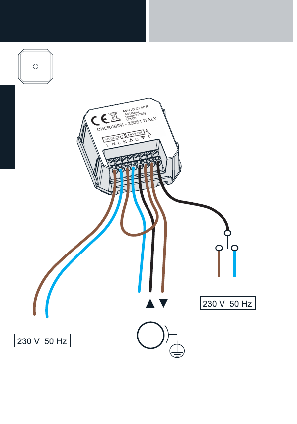
MAGO Control unit A510051 for standard wiring motor ...................................... p. 26
MAGO Control unit A510051 for RX white wire motor ......................................... p. 27
MAGO Actuator A510048 ON/OFF for two independent loads ............................. p. 28
MAGO Actuator A510048 thermostat ................................................................... p. 29
MAGO Dimmer A510047 ...................................................................................... p. 30
MAGO Gateway A510049 ..................................................................................... p. 31
APP INSTALLATION
Installing the MAGO application .......................................................................... p. 32
SYSTEM CREATION
MAGO system creation ........................................................................................ p. 33
Device association ............................................................................................... p. 34
Device identication ............................................................................................ p. 34
App-assisted identication ................................................................................... p. 34
Description of the main screen ............................................................................. p. 35
SYSTEM CONFIGURATION
MAGO system conguration ................................................................................. p. 36
MAGO Switch and MAGO Control Unit advanced settings menu ......................... p. 37
MAGO Actuator advanced settings menu ............................................................. p. 38
How to connect MAGO Gateway to the Cloud ...................................................... p. 39
How to remove a MAGO item from the system ..................................................... p. 39
How to add a MAGO item to the existing system ................................................. p. 39
Main menu ............................................................................................................ p. 40
Adding a smartphone to an existing system .......................................................... p. 40
MAGO devices reset .............................................................................................. p. 41
Technical features .................................................................................................. p. 42
Conformity ............................................................................................................ p. 103
23
ENGLISH

25
MAGO DEVICES AND
ELECTRICAL CONNECTIONS
APP INSTALLATION
INTRODUCTION
MAGO DEVICES:
Device Positioning Specialisation CH motor
compatibility
MAGO Switch Wall-mounted with
built-in box
Shutter, Awning, Screen,
Venetian blind
Standard wiring
MAGO
Control unit
Flush-mounted Shutter, Awning, Screen,
Venetian blind, Adjustable
roller shutter
Standard wiring
Wiring with white
lead
MAGO
Actuator
Flush-mounted 2 stable independent outputs
2 independent impulsive
outputs
2 independent timed outputs
1 switching output (diverter)
1 switching thermostat
output
MAGO
Gateway
Tabletop Cloud access
Temperature and humidity
sensors
MAGO
Dimmer
Flush-mounted 2 independent LED outputs
MAGO is a system consisting of various devices connected to each other via Bluetooth
in a mesh network. The system can be expanded adding other devices at any time; this
allows considerable distances to be covered - even across different oors. The system
is only accessible via the MAGO application downloaded to a smartphone. The data
exchanged on the system are encrypted and can only be accessed from MAGO devices
using the system password, or from smartphones with access authorisation. This makes
of MAGO a highly secure system protected from unauthorised access.
Maximum system capacity:
192 devices, 15 units, 16 scenes, 16 environments, 250 events.
24
ENGLISH

SYSTEM
CREATION
SYSTEM
CONFIGURATION
25
MAGO Switch A510046
L1 N
C
M
Wall-mounted button panel for standard wiring motors.
APP INSTALLATION
MAGO DEVICES:
Device Positioning Specialisation CH motor
compatibility
MAGO Switch Wall-mounted with
built-in box
Shutter, Awning, Screen,
Venetian blind
Standard wiring
MAGO
Control unit
Flush-mounted Shutter, Awning, Screen,
Venetian blind, Adjustable
roller shutter
Standard wiring
Wiring with white
lead
MAGO
Actuator
Flush-mounted 2 stable independent outputs
2 independent impulsive
outputs
2 independent timed outputs
1 switching output (diverter)
1 switching thermostat
output
MAGO
Gateway
Tabletop Cloud access
Temperature and humidity
sensors
MAGO
Dimmer
Flush-mounted 2 independent LED outputs
24
ENGLISH

27
MAGO Control unit A510051
Flush-mounted control unit for standard wiring motor
26
L1 N
M
C
L1 N
optional
control
ENGLISH
MAGO DEVICES AND
ELECTRICAL CONNECTIONS
APP INSTALLATION

MAGO Control unit A510051
Flush-mounted control unit for RX white wire motor
27
L1 N
L1 N
optional
control
L1 N
L1 N
M
MAGO Control unit A510051
Flush-mounted control unit for standard wiring motor
26
optional
control
ENGLISH
SYSTEM
CREATION
SYSTEM
CONFIGURATION
APP INSTALLATION

2928
MAGO Actuator A510048
ON/OFF actuator for two independent loads.
L1 N
optional
control
L1
U1
U2
optional control
U1 U2
1 ON ON
2 OFF ON
3 ON OFF
4 OFF OFF
ENGLISH
MAGO DEVICES AND
ELECTRICAL CONNECTIONS
APP INSTALLATION

29
MAGO Actuator A510048
Thermostat actuator.
THERMOSTAT INPUT
BOILER/AIR CONDITIONER
CONTACT NO
28
optional
control
optional control
U1 U2
1 ON ON
2 OFF ON
3 ON OFF
4 OFF OFF
ENGLISH
SYSTEM
CREATION
SYSTEM
CONFIGURATION
APP INSTALLATION

31
MAGO Gateway’s two main features are:
1) Connection to the Cloud, i.e. ability to remotely access the Mago system via Wi-Fi or a
GPRS connection.
2) Through the temperature and humidity sensors integrated in the device, MAGO
Gateway allows these values to be displayed on the application home page.
Temperature data can also be used by the specialised thermostat MAGO Actuator, to
manage the activation or deactivation of the boiler or air conditioner.
MAGO Gateway is an optional unit: the system will work even without this device.
Front LED description:
Steady red: it indicates that the Cloud conguration is not complete or has not been
implemented.
Slow green: it indicates that the connection to the network has not yet been made, or
that logging in to the GPRS network has not occurred.
Fast green: it indicates that logging in to the network has been successfully performed,
or that IP connection from the GPRS network has been obtained.
Steady green: it indicates that the gateway is connected with the server.
Steady green + ashing red: it indicates that the gateway is temporarily unavailable
because updating is in progress.
Blue: it indicates the reception of a Bluetooth package.
MAGO Dimmer A510047
Low voltage device to control 2 LED bars.
30
optional
control
12/24 V DC
STRIP LED 1
STRIP LED 2
+
+
+
ENGLISH
MAGO DEVICES AND
ELECTRICAL CONNECTIONS
APP INSTALLATION
Ce manuel convient aux modèles suivants
5
Table des matières