6
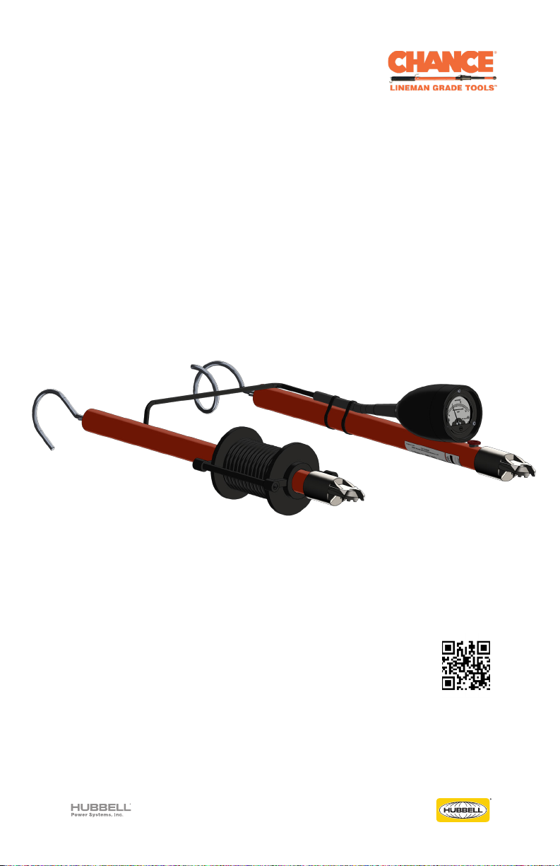
©2022 Hubbell Incorporated | Chance®Phasing Meter Operating Instructions
Overhead Operation
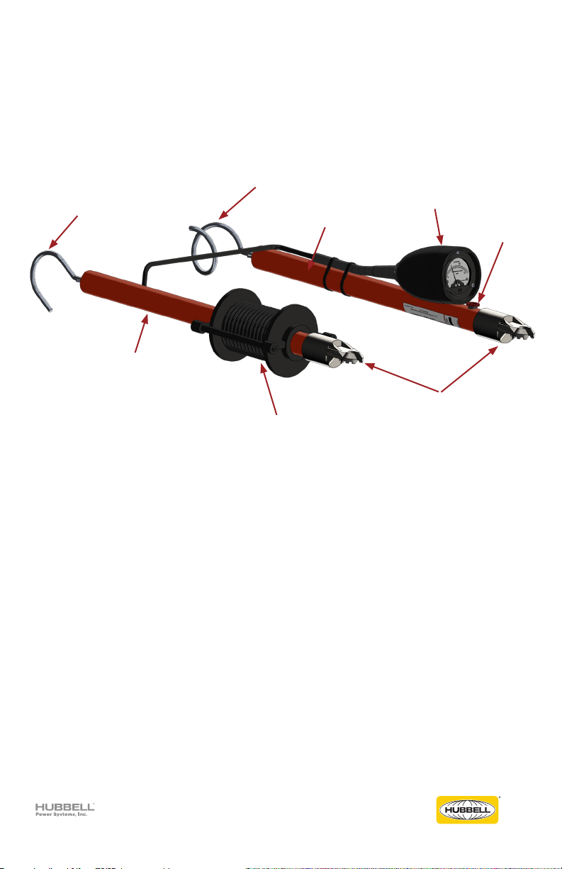
The Phasing Meter is equipped with a cable reel on which the cable between the two housings
is stored.
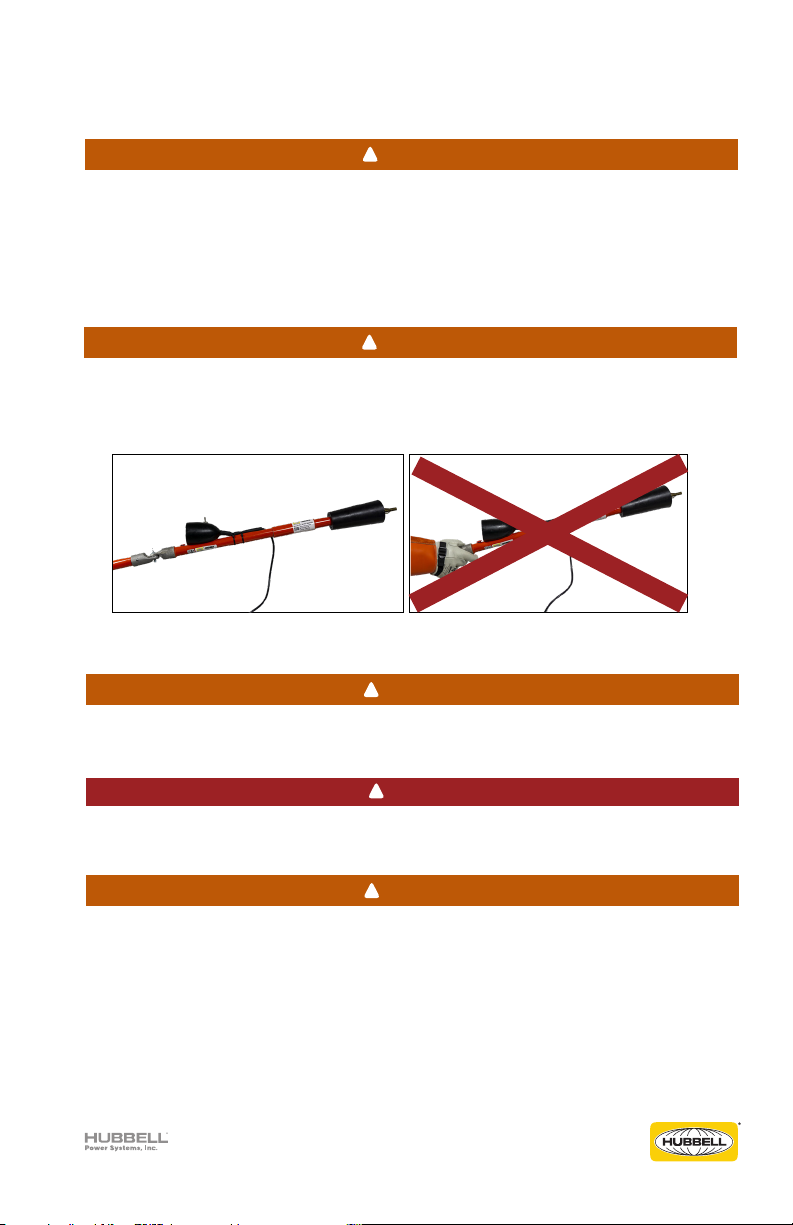
During high voltage testing, only use the length of cable necessary to permit the contacts
to reach between the points of measurement. Any remaining cable length should be kept
wound on the reel.
There are two reasons for this:
1. Cable insulation is limited to 15 kV for light weight and ease of handling. This is adequate
for momentary contact with ground of 15 kV conductors but damaged insulation may
result in an uncomfortable shock if personal contact is made at a damaged area. At higher
voltages, insulation puncture may result. KEEP CABLES FROM CONTACT WITH OTHER
MATERIAL OR PERSONNEL.
2. Meter indications will be aected and error introduced by the capacitance to ground
between the cable and grounded structure, moist concrete, or the earth. Other conductors
will also influence meter indications if the cable is allowed to touch or come in close
proximity to these conductors. RESISTOR ENCLOSURE PORTION CAN PUNCTURE ABOVE
40 kV. KEEP THIS PORTION CLEAR OF CONDUCTORS, STRUCTURES, AND GROUNDS.
This tool is not intended for continuous contact application. Tests at full voltage for 30
minutes produced no damage, although heating of resistors did occur. Contact should be
limited to the time required to note the meter indication.
To measure line-to-ground voltage, the section on which the meter is mounted should
preferably be used at the ground potential contact to minimize stray capacitance influence on
the meter. On line-to-line measurements, contact is made to each phase conductor keeping
connecting cable away from other conductors, grounded or metal structures, and
isolated from contact with platforms or each contact. As noted before, this is to avoid
influence which may distort meter indications.
In tying two energized 3-phase feeders together where it is necessary to match phases,
voltage measurements must be made between a conductor of one circuit and each of
the conductors of the second circuit. This procedure is followed for each phase to avoid
connecting phases in reversed rotation. Re-check the third phase just before making the final
connection to assure proper phase relationship. With matched phases one may expect the
voltage indication to be near zero. More often a voltage will be indicated due to phase shift at
the open point in remotely energized circuits and/or unequal voltage drop. Proper connections
can readily be determined by the meter indications. Preliminary phase-to-phase measurements
of each circuit are recommended to determine that proper voltages are being connected.
In substations, bus and switchgear cubicles, or other crowded areas where electrical fields
are of greater intensity, extra precaution is recommended to avoid disturbing influences
aecting meter indications.
!CAUTION
!CAUTION
!CAUTION