CGM MDR-01 Manuel utilisateur

Operation’s manual Rheometer MDR-01
1
1. Specifications
- Reference Standard
ISO 6502, ASTM D5289
- Pressure system
Air cylinder system
- Die configuration
Biconical Die, close die system, sealed
- Temperature System
PID Microprocessor Controlled
Probe RTD Pt 100 Ω(Class A)
- Temperature range
Room Temp. (+25 °C) to 250 °C
Resolution 0.1
°C Units °C/ °F
- Oscillation frequency
100 cpm. (1.667 Hz)
- Oscillation angle
0.5°±0.03°, 1°±0.03°
- Drive Motor
Servo Motor
- Torque Measurement
Torque Transducer (Direct Torque Measurement)
- Torque Calibration
Standard Torque Reference value
- Operation Panel
Capacitive Touch Screen, 5 Inches (Standalone)
- Measured Time
1/60 sec, 1/100 sec
Unit (min-min/ min-sec/ sec)
- Communication Data
RS-232
- Associated program (Option)
Data Process Software
- Power Supply
220 VAC ±10 VAC, 50/60 Hz, 6 A
- Air Pressure
4.0 bar to 5.0 bar
- Dimension
Width 50.0 cm., Depth 54.5 cm., Height 105 cm.
- Weight
140 kg.

Operation’s manual Rheometer MDR-01
2
2. Components
1
2
5
3
6
4
Figure 1 Front image of the MDR-01
Figure 1, illustrates the components of the front perspective of the MDR -01, as follows;
No. 1: The Upper Plate, which consists of the Upper die, Heater, and Probe Sensor
No. 2: The Lower Plate, which consists of the Lower die, Heater, and Probe Sensor
No. 3: Display panel
No. 4: Emergency Stop button
No. 5: On/Off plate switch
No. 6: On/Off motor switch

Operation’s manual Rheometer MDR-01
3
8
7
9
10 11
Figure 2 Internal Components of the MDR-01
Figure 2, illustrates the internal components of the MDR -01, as follows;
No. 7: Servo Motor
No. 9: Transformer
No. 8: Thermostat
No. 10: Adjustable leg stand
No. 11: Main control panel

Operation’s manual Rheometer MDR-01
4
12
14 13
Figure 3 Side image of the MDR-01
Figure 3, illustrates the side perspective of the MDR -01, as follows;
No. 12: RS323 outlet for connection to a computer or printer
No. 13: Power outlet (220 VAC)
No. 14: On/Off breaker switch
Operation’s manual Rheometer MDR-01
5
15
18 16
17
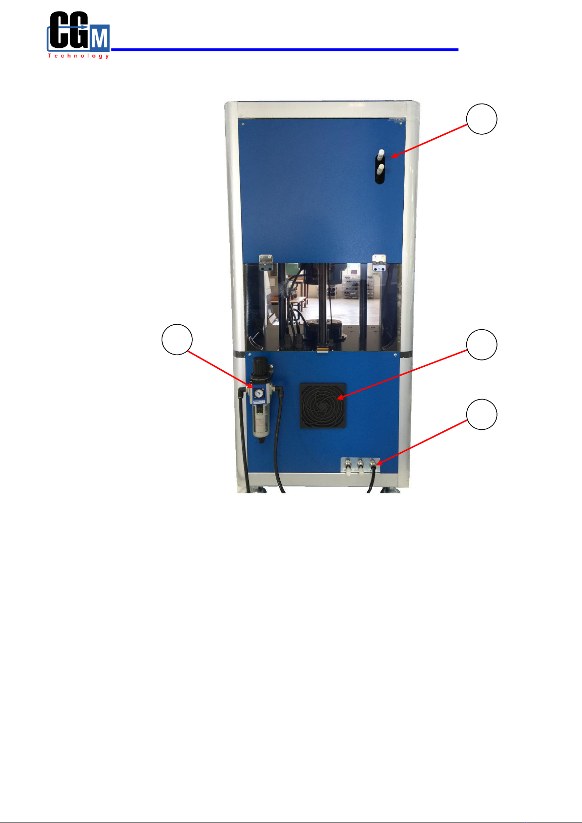
Figure 4 Rear image of the MDR-01
Figure 4, illustrates the rear components of the MDR -01, as follows;
No. 15: Air Muffler
No. 16: Air ventilator
No. 17: Air intake, which is connected to the Air Regulator
No. 18: Air Regulator

Operation’s manual Rheometer MDR-01
6
3. Installation
3.1) For the installing technician
1. Set the device to a level position
3.2) For users
1. Site preparation for the installation of MDR-01
- Grounded power outlet with a 220 VAC 50Hz/60Hz capacity, that can
discharge at no less than 6 Amp
- Compressed air supply of at least 4-5 bars
- Support structure to place the MV-01, which can withstand a weight of
200 kg. or more.
2. Installation instructions for the Rheometer MDR-01
- Recommended to be used in conjunction with a UPS with a minimum
capacity of 1.5KVA or more.
- Recommended to be installed in rooms with temperature and humidity
control.

Operation’s manual Rheometer MDR-01
7
4. How to use the touch screen panel of the Rheometer MDR-01
After powering up the MDR-01, the main screen display will be as indicated in
Figure 5, which is used for monitoring and tracking of the test results. The main functions
will consist of Testing, Condition, Calibrate, and Configuration.
Figure 5 Image of the Main Screen display
1. Testing Displays the results of the test in a graphical format.
2. Condition Sets the conditions or state of the sample to be tested.
3. Calibrate Sets the testing and calibration of the TORQUE STANDARD
4. Configuration Monitors the status and parameter settings, and stores them in
the device’s memory.
4.1) Testing
By pressing the “Testing” button, will enter into the testing mode, in which the
function consists of 4 sections; STANBY, RESULT, GRAPH, and CLOSE. See
Figure 6.

Operation’s manual Rheometer MDR-01
8
A
Figure 6 shows the main display of the Testing mode
Figure 7 shows the resulting display when A is selected
Note: Pressing A area on touch screen for switching the display between Figure 6
and Figure 7.

Operation’s manual Rheometer MDR-01
9
4.1.1) STANBY is the ready function, waiting for the samples to be tested.
See example below.
Figure 8 shows the display screen in the STANBY mode
4.1.2) RESULT, will show the test results, as can be seen in Figure 9.
Figure 9 shows the display of the RESULT function
Components of the Test results
1. MH : Value of highest torque
2. ML : Value of lowest torque

Operation’s manual Rheometer MDR-01
10
3. ts1 : Scorch time 1, time from the start where torque equal
ML to the time where torque equal ML+1
4. ts2 : Scorch time 2, time from the start where torque equal
ML to the time where torque equal ML+2
5. tc10 : Cure time at 10%
6. tc50 : Cure time at 50%
7. tc90 : Cure time at 90%
Note: Cure time 100% is time from the start of the test where lowest torque
value (ML) is reached highest torque value (MH)
4.1.3) GRAPH, displays the sample test results in a graphical format and its
associated numerical values, as shown in Figure 10
Figure 10 displays the GRAPH function
4.1.4) CLOSE, controls the On/Off function of the Plate and Die
Status
RED, Plate has been closed, and sample testing is in progress.
GREEN, Plate is open, and sample testing is waiting to be tested
Table des matières
Manuels Instrument de mesure populaires d'autres marques


Endress+Hauser
Endress+Hauser Proline Promag 50 Caractéristiques techniques

Siemens
Siemens SITRANS F Coriolis FCT030 Manuel de la liste des pièces

KLINGER
KLINGER CMF V Series Manuel utilisateur

EXFO
EXFO FTB-2 Manuel d'exploitation et d'entretien

Keysight
Keysight M8290A Manuel utilisateur

ADTEK
ADTEK MW-5 Manuel utilisateur