GALEO
Illuminated RF Keypad
INSTALLATION MANUEL
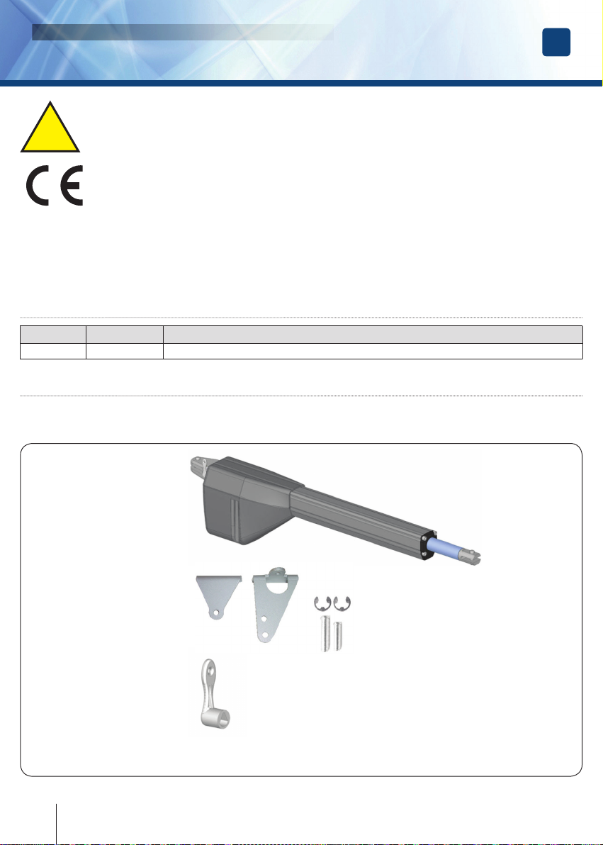
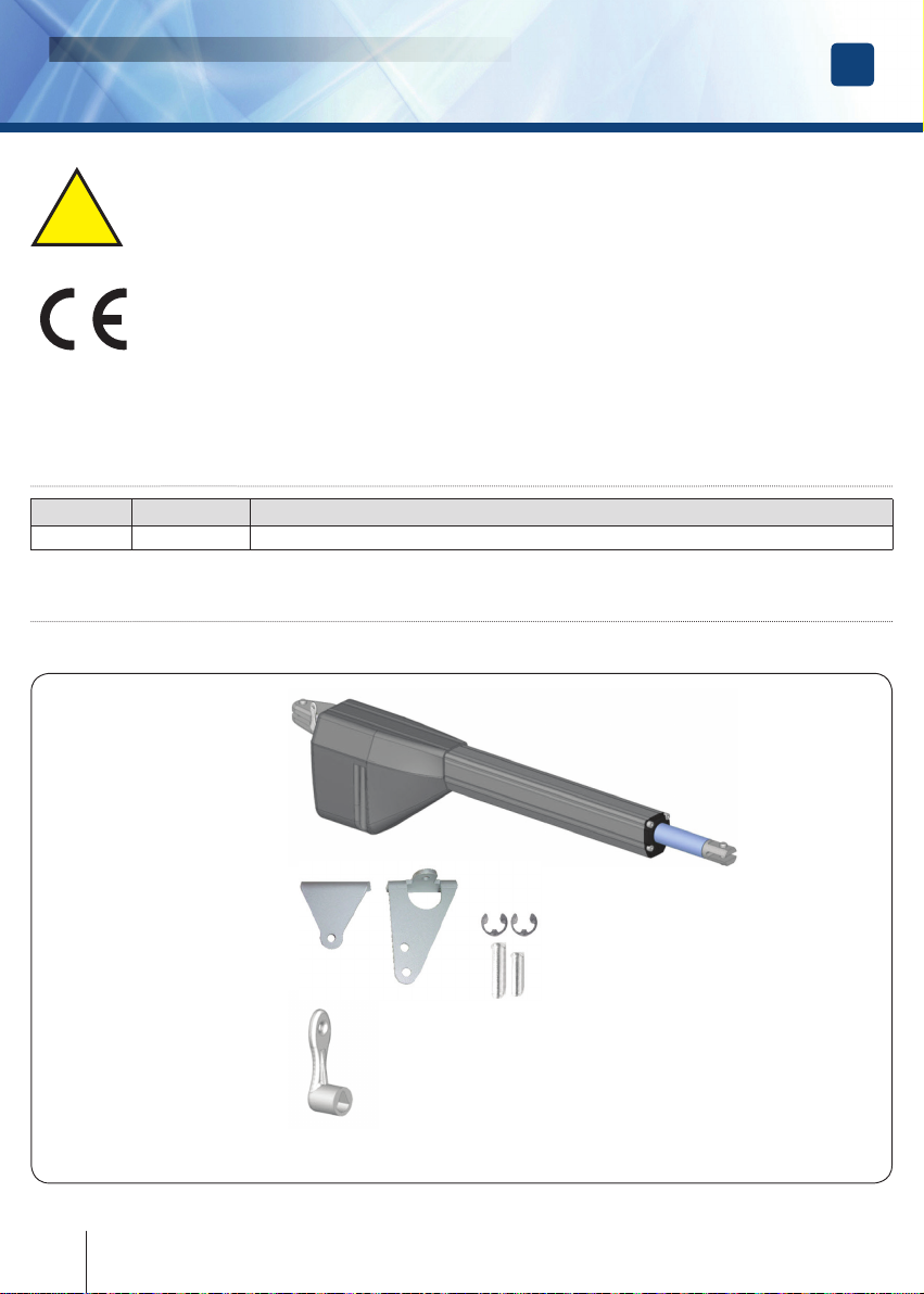
EGO
Electromechanical operator for swing gates
INSTALLATION MANUAL EN
7
erone.com
10] Troubleshooting
Drawback Probable cause Solution
The gate doesn’t open or the motor
doesn’t move after a command from
remote control, key switch
Line power absent Check the main switch
Emergency STOP active
Check for any the selectors or STOP
commands. If not used check the
presence of the bridge on the STOP
input on the control panel
Blown Fuse Replace it with another identical or of
the same value
Motor power cord
disconnected or defective
Connect the motor power cord to the
corresponding terminal or replace it
Obstacle on the photocells
beam
Check the connection and / or remove
the obstacle
The command is executed by the
key switch and not by the remote
control
The remote control has
not been memorized or its
battery is low
Check the memorization of the remote
control on the receiver of the control
panelor replace the transmitter battery
The gate starts but stops
immediately
the torque of the motor(s) is
insufcient
Change the torque useing the trimmer
“Torque” on the control panel
One leaf opens and the other closes The wiring of the motor is
wrong
Swap the wires polarity of the faulty
motor
INSTALLATION RECOMMENDATIONS
• The installation must be performed by professionally competent personnel and in compliance with applicable
local, state, national and European legislation.
• Before starting the installation check the integrity of the product.
• Installation, electrical connections and adjustments must be made a “Rule of art”.
• Packaging materials (cardboard, plastic, polystyrene, etc.) must not be released into the environment and
must not be left within reach of children as potential sources of danger.
• Do not install the product in areas where there is a danger of explosion or high electromagnetic elds. The
presence of ammable gases or fumes is a serious danger for the safety.
• Provide protection against overvoltage on the power supply network, a switch / disconnector and / or
differential suitable for the product and in compliance with the current regulations.
• The manufacturer declines all responsibility if devices are installed and / or incompatible components for the
purposes of product integrity, safety and safety operation.
• Only original spare parts should be used for repairing or replacing defective parts.
• The installer must provide all information regarding operation, maintenance and the use of the individual
components, parts and the whole system.
WARNINGS FOR THE USER
Read carefully the instructions and the attached documentation.
The product is intended for the used for which it was expressly designed. Every different use mus be considered
improper and therefore dangerous. Furthermore, the information contained in this document and in the attached
documentation, may be subject of changes without notice. They are, in fact, provided as an indication for the
application of the product. The manufacturer declines any and every responsibility. Keep products, devices,
documentation and anything else out of the reach of children.
In case of maintenance, cleaning, breakdown or malfunction of the product, remove power, avoinding any attempt
of intervention. Contact only professional and competent personnel, responsible for the purpose. Failure to
comply with the above warningd can cause situations of serious danger.