CASPR Pro Manuel utilisateur

CAUTION: Read manual carefully for proper procedures and operation.
The information in this manual is applicable to these HVAC units:
CASPR Pro 400 | CASPR Pro 1000 | CASPR Pro 2500 | CASPR Pro 5000
PRo Owner’s Manual

2
Congratulations
on your purchase of a CASPR Group enhanced air and surface disinfection system.
This unit is designed to be mounted into central HVAC duct systems. Please read
and follow all safety warnings and service procedures outlined in this manual. Use
only genuine CASPR Group replacement parts available from your CASPR Group
Distributor.
If you have any questions concerning this or any CASPR Group product, contact your
CASPR Group Distributor.
Principles of Operation
CASPR PRO uses Natural Catalytic Conversion (NCC) to generate safe, low levels
of hydrogen peroxide. NCC technology replicates natural purifying processes
by using a high intensity light to activate a proprietary metal catalytic coating,
converting water vapor into hydrogen peroxide. Hydrogen peroxide acts as an
oxidizer inactivating surface and air pathogens. It can compromise cellular integrity
by disrupting cell walls, or internal molecular structures, rendering contaminants
harmless.
To learn more about this and other CASPR Group products and technologies, please
visit our website at www.CASPRgroup.com.
Table of Contents
Warnings....................................................................................................3
Specications..............................................................................................4
Product Contents ........................................................................................4
Installation Hardware ..................................................................................5
Replacement Parts ......................................................................................5
Recommended Installation Tools....................................................................5
Electrical Requirement..................................................................................6
Hard-Wiring Requirement..............................................................................6
Installation Requirement...............................................................................6
Orientation and Airow ................................................................................7
Installation Instructions ...............................................................................8
Alternative Cutting Method............................................................................9
Installation (continued)...............................................................................10
Hardwire Instructions .................................................................................11
Hardwire Instructions (continued) ............................................................... 12
Indicator Lights .........................................................................................13
Maintenance..............................................................................................14
Disposal Of The NCC Cell.............................................................................14
Changing The NCC Cell................................................................................14
Changing The NCC Cell (continued) ..............................................................15
Troubleshooting Q&A ..................................................................................16
Warranty Information .................................................................................17

3
IMPORTANT SAFETY INSTRUCTIONS
When using an electrical appliance, basic precautions should always be taken.
READ ALL INSTRUCTIONS BEFORE USING THIS PRODUCT
WARNING!
To reduce the risk of re, electrical shock, or injury:
• Use only as described in this manual.
• Do not attempt to repair or adjust any of the electrical or mechanical functions.
Contact Customer Service for service information.
• Do not use outdoors or on wet surfaces.
• Do not allow to be used as a toy. Do not allow children around the unit.
• Do not handle with wet hands.
• Do not touch NCC bulb with bare hands.
WARNING
WARNING! - UV light in operation. Disconnect unit from
power supply before servicing. Failure to follow warnings
may result in severe eye damage.
WARNING! - Unit should be mounted at least 24 inches
from the heat exchanger or heating element. Placing the
photocatalytic cell too close to the heating element can
cause the photocatalytic matrix to combust.
To reduce the risk of electric shock, this equipment may have
a grounding type plug that has a third (grounding) pin. This
plug will only t into a grounding type power outlet. If the
plug does not t into the outlet, contact an HVAC professional
to install the proper outlet. Do not alter the plug in any way.

4
Specications
Unit Coverage Size (HxWxD)* Weight Watts Amps
DC 24V
Amps
AC
120V
CASPR Pro 400 4,000 ft39.75” x 9.75x 8” 3.0 lb 80.52 0.28
CASPR Pro 1000 10,000 ft39.75” x 9.75” x 11” 3.1 lb 10 0.64 0.30
CASPR Pro 2500 25,000 ft39.75” x 9.75” x 16.75” 3.3 lb 18 1.0 0.44
CASPR Pro 5000 50,000 ft310” x 11.3” x 16.75” 5.0 lb 36 2.0 0.74
* Hard-wired power supply: 4.7” x 4.7” x 1.6”
NCC Cell
Mounting
Bracket
Ballast Housing
Power supply
(Hardwired)
Power supply
(Plug-in)
Product Contents

5
A
A - 4” Hole Saw Bit
B - 3/8” Drill Bit
C - Drill/Power Driver
B C D EF
D - Utility Knife
E - Tin Snips
F - Phillips Head Screwdriver
(8) #8 3/4 Hex Self-tapping Screws
(4) Flange Nuts
(2 or 4) Cell Mounting Screws (2 screws per NCC Cell)
The NCC Cell and bulb should be replaced every 18-24 months. Please
contact your distributor for new replacements.
CASPR Pro 400 NCC Cell Part Number: CELL-HV-5-001-AP
CASPR Pro 1000 NCC Cell Part Number: CELL-HV-9-001-AP
CASPR Pro 2500 and 5000 NCC Cell Part Number: CELL-HV-14-001-AP
Installation Hardware
Replacement Parts
Recommended Installation Tools

6
All CASPR Pro duct mounted units run on DC 24V. Each unit comes with a power
adapter that will take AC 100-240V. We recommend locating the unit within 6 ft. of
a standard 120V Grounded outlet to plug in directly. Long term use on an extension
cord is not recommended due to safety considerations.
If an outlet is not available within 6 feet of the instillation location, you may hardwire
the unit into the HVAC system using a licensed HVAC professional.
Permanent wiring of the unit into your HVAC system may be completed using a hardwire
assembly (sold separately) and should be done by a licensed HVAC Installer or Electrical
Contractor only.
For 110V or 220V Applications: Black = L1, White = Neutral,
Green = Ground
For International Applications: Brown = L1, Blue = L2,
Green/Yellow = Ground
If DC 24V is available, splice the wire between the brick and the cell housing to wire
directly to the unit circumventing the power brick.
If the voltage is higher than AC 120-240V, you will need a transformer that converts
your supply voltage to DC 24V eliminating the power brick.
When hardwiring any of these units please be mindful of the Maximum Amp draw
that your power supply transformer can handle to prevent damage (Equation: Power
Supply Transformer Amps / CASPR Volts = Maximum Amp Load).
Electrical Requirement
Hard-Wiring Requirement
1. Unit should be installed downstream
of the air handler in the HVAC
system.*
*Additional HVAC units are
recommended in the Return Plenum
for added protection and to keep the
internal parts clean.
2. The duct work around the installation
area should be cleaned and dry to
insure proper adhesion of the gasket
materials and any tape used.
3. One-two 4” circular openings will
need to be cut into the existing duct
work to install the unit properly. (2-
for CASPR Pro 5000; 1-CASPR Pro
400, 1000, 2500).
HVAC Supply Plenum
HVAC Return Plenum
(Recommended Option)
Installation Requirement

7
Orientation and Airow
When installing the CASPR Pro
5000, make sure the airow moves
through the NCC cells as indicated
by the blue arrow.
Make sure, when installing several
units at once, that they are
staggered to minimize overlap of
NCC cells and maximize airow.
When installing the CASPR Pro
400, 1000, and 2500 make sure
the airow moves through the
NCC cells as indicated by the blue
arrow.
Make sure, when installing several
units at once, that they are
staggered to minimize overlap of
NCC cells and maximize airow.

8
1. Find a suitable location to mount your
Unit.
2. If necessary, cut away insulation for
your plate to adhere to the duct.
3. Using the Adhesive Mounting Bracket,
trace the hole location onto the duct.
Keep in mind the CASPR Pro 5000
orientation before cutting (Refer to
orientation and airow above).
4. Use the Hole Saw and Drill to cut out
the marked hole.
Installation Instructions
Diagrams are representative of the CASPR Pro 400, 1000, and 2500. The steps
are the same for the CASPR Pro 5000 with slight variations in orientation and
number of holes. Please refer to the airow and orientation section above for
proper installation of all models.

9
1. Using the Adhesive Mounting Bracket,
trace the hole location onto the duct.
Keep in mind the CASPR Pro 5000
orientation before cutting (Refer to
orientation and airow above).
2. Drill holes around the outside edges
of the previously marked hole
but inside the outer holes of the
Adhesive Mounting Bracket.
3. Use the Tin Snips to cut out the
space around the marked hole.
4. Remove the plastic backing on your
Adhesive Mounting Bracket.
Alternative Cutting Method
10
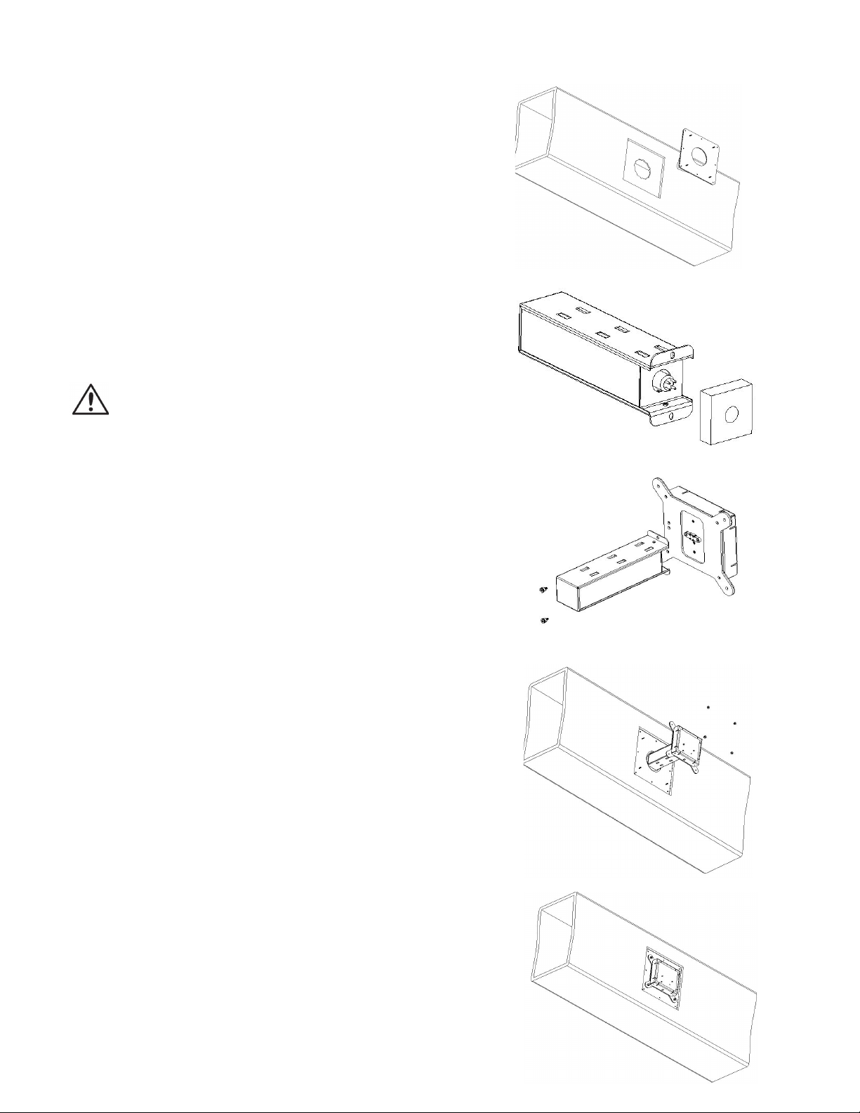
5. Press the Adhesive Mounting Bracket
onto the duct. Secure with the (8 Self-
Tapping Screws.
6. Remove the packing foam from the
NCC Cell
7. Connect the Cell to the Ballast
Housing using the (2) Cell Mounting
Screws provided. Repeat this step if
you have a double cell unit.
8. Place the unit and cell through the
opening and align the four studs with
the four holes in the Ballast Housing.
Secure the unit with the (4) Flange
Nuts until it is ush with the duct.
MAKE SURE THE AIRFLOW MOVES
THROUGH THE NCC CELL (Refer to
orientation and airow above).
9. Plug the Power Cable into the
receptacle or have a Licensed
Electrician or HVAC Installer hard
wire the unit directly into the HVAC
system.
Installation (continued)
DO NOT TOUCH BULB WITH BARE HANDS
Ce manuel convient aux modèles suivants
4
Table des matières
Autres manuels CASPR Purificateur d'air

CASPR
CASPR 200 Manuel utilisateur

CASPR
CASPR TRANSIT 120V Manuel utilisateur

CASPR
CASPR Compact Manuel utilisateur

CASPR
CASPR MOBILE Manuel utilisateur

CASPR
CASPR BLU TILE Manuel utilisateur

CASPR
CASPR MEDIK Manuel utilisateur

CASPR
CASPR MINI Manuel utilisateur

CASPR
CASPR Compact Manuel utilisateur

CASPR
CASPR TILE Manuel utilisateur


