CASI RUSCO 660 Manuel utilisateur

Part Number: 460221001 Rev. C
September 1998
Model 660
Keypad
Installation Guide
CASI
RUSCO
1155 Broken Sound Parkway NW
Boca Raton, Florida 33487
(561) 998-6100
CASI-RUSCO...Security Solutions for the 21st Century

This publication may contain examples of data reports used in daily
business operations. Examples include fictitious names of individuals
and companies for illustration only; any similarity to names and
addresses of actual business enterprises and persons is entirely
coincidental.
This document is distributed on an as is basis, without warranty either
expressed or implied. Successful implementation depends solely upon
the customer’s ability to integrate each product into the total inventory
of “in-house” products. While each offering has been reviewed for its
compatibility and maintainability, no assurance of successful
installation can be given.
The customer accepts full maintenance responsibility. (A full scope of
software and hardware maintenance contracts are available to the
customer.)
Copyright 1994, 1998 CASI-RUSCO
All Rights Reserved
Printed in the USA

Model 660 Keypad
i
Contents
Introduction ................................................................................................ 1
Product Features......................................................................................... 1
Connecting the Keypad............................................................................. 2
Programming the Keypad......................................................................... 6
Testing the Keypad.................................................................................... 7
Technical Specifications............................................................................. 8
Functional Specifications........................................................................... 9

Model 660 Keypadii

Model 660 Keypad 1
Introduction
This manual is an installation guide for the CASI-RUSCO Model 660
Keypad. The Model 660 uses 26-bit Wiegand technology. The Model 660
features an audible keypad; an annunciator beeps with each key press.
Note: PIN (Personal Identification Number), as referenced in this Installation
Guide, is the Badge Number in the host system.
Product Features
The CASI-RUSCO Model 660 Keypad offers:
•State-of-the-art architecture.
•Weatherproof housing for outdoor use.
•Rugged molded construction.
•5V operation.
•A clear, logical user interface with two LEDs and a beeper.

2Model 660 Keypad
Connecting the Keypad
The table below shows the pinouts for connecting the keypad to the
microcontroller. TABLE 1: Pinouts
Signal Pigtail wire color
+5 VDC Red
Ground Black
Green LED Brown
Reader Data 0 Green
Reader Data 1 White
Site Codea
a. See “Programming the Keypad” on page6.
Yellow or Pink
Hold Line Control Orange
Ground (case)b
b. Connect to black wire. Ground at keypad installation point; do not
ground through cable.
Tan
30 Second Outputc
c. Pressing any keypad button will generate a 30-second, 0.25-amp
output to ground. (This can be used to activate a CCTV or similar
device.)
Blue

Model 660 Keypad 3
FIGURE 1: Pinout Diagram
Note: If you cannot find a color, go by the position in the connector.
BROWN
BLACK
ORANGE (NO CONNECTION)
RED
WHITE
GREEN
YELLOW
TAN
BLUE
PINK
JUMPER MUST BE INSTALLED
IF PRESENT

4Model 660 Keypad
FIGURE 2: Wiring Diagram, Model 660 26-bit Wiegand Output

Model 660 Keypad 5
Notes: Unless otherwise specified:
1
. For Micro/5 only: two 470 ohm, 1/2W, pull-up resistors may be required if the cable run is greater than 200ft; one
between +5VDC and READER DATA 1, the other between +5VDC and READER DATA 0. The pull-up
resistors should be installed at the microcontroller’s terminal block. The maximum cable distance is 300ft.
2
. For Micro/2/4: Keypad must be connected to the micro using an amp card or junction box. These should be
placed as close to the reader as possible. See appropriate system manual for details.
3
. Shielded cable is required. Belden 8725 wire is recommended. Do not pair DATA 1 and DATA 0.
4
. If using shielded cable, connect all shields together at the micro end. Connect to ground stud in the lower left
corner of Micro/2/4/5 cabinets using 14-AWG wire. No shield connections at the keypad.
5
. If using a local power supply, do not connect +5V line from the microcontroller to the keypad. However, the
negative side of the power supply must be connected to the micro (pin 2 on the reader port). Keep the wiring
from power supply to keypad less than 50 feet.
6
. See the appropriate system manual for specific wiring details.
7
. Blocking diodes may be 1N4148 or similar, supplied by the installer, and located in a secured area.
8
. Protection diodes may be 1N4002, 1N4003, or 1N4004 (installer supplied) for the door strike assembly.

6Model 660 Keypad
Programming the Keypad
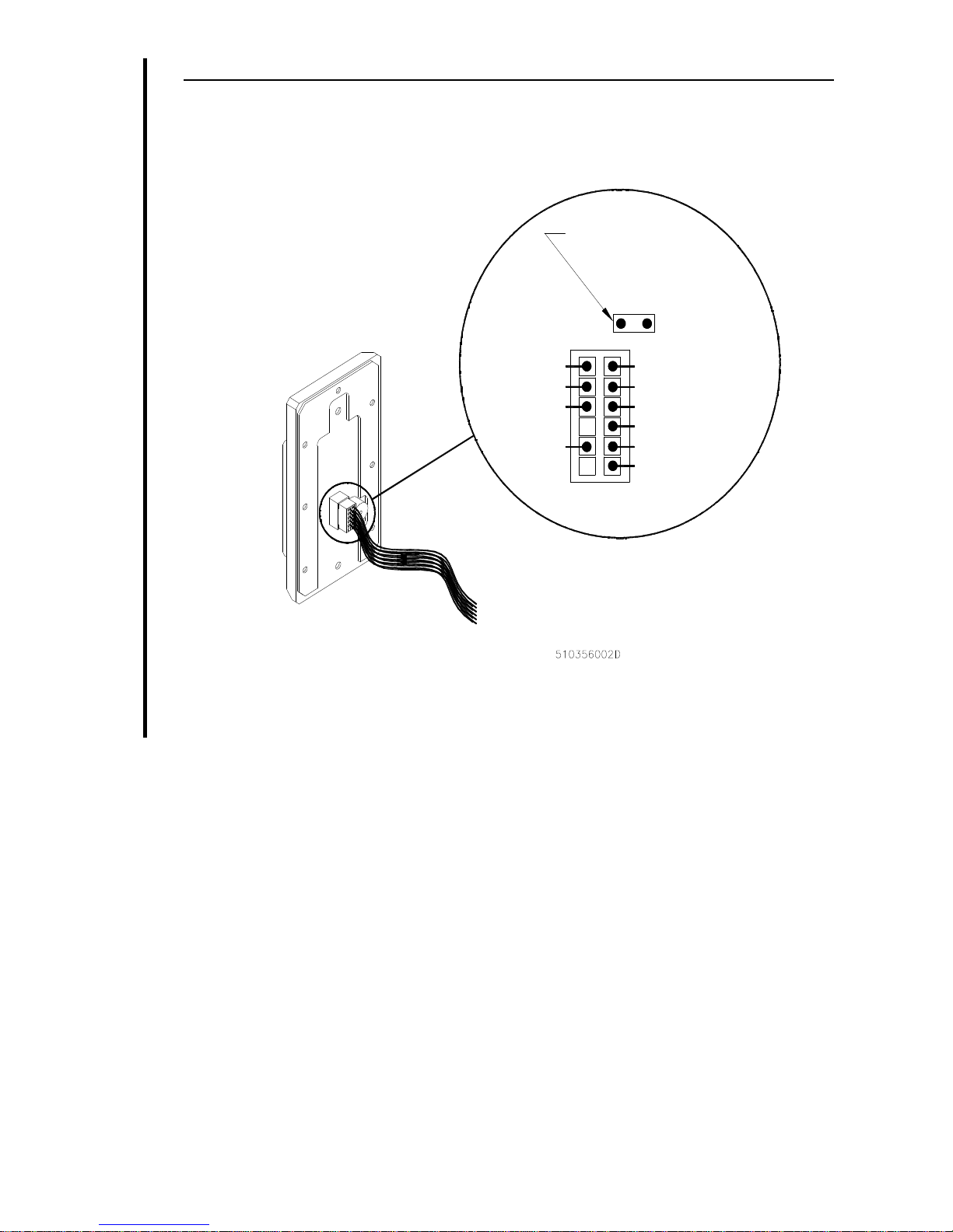
Current Model Keypad: This keypad is capable of having the site code
programmed in the field. The PINK wire is used in this procedure. With
no voltage applied to the keypad, connect the PINK wire to the BLACK
wire on the wiring harness. Apply the appropriate voltage to the RED
and BLACK wires. You will hear 4 rapid audible beeps and both the RED
and the GREEN LEDs will flash at the same rate. Enter the desired site
code (between 001 and 255) on the keypad and press # for enter. (The site
code MUST be 3 digits only and 000 is not an acceptable site code. Site
code 00001 would be entered as “001”; 00123 would be entered as “123”.)
You will again hear 4 rapid audible beeps and see both LEDs flash 4
times. At this point, the keypad will appear dead and will not accept any
entries.
If a wrong key is pressed during the programming experience, pressing
the * key will clear the entry. You will hear 2 rapid beeps and both LEDs
will flash at the same rate. (The keypad will generate a long error tone if
you enter a site code over 255.)
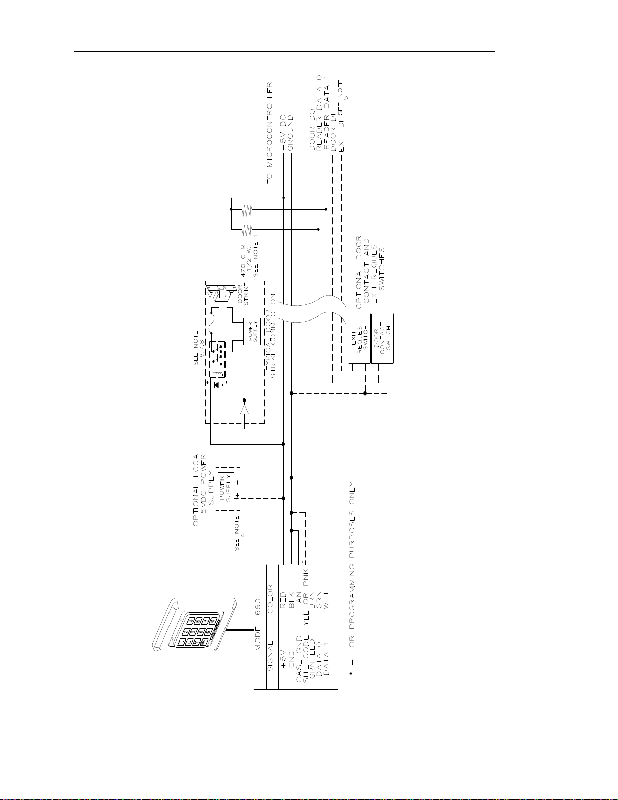
Disconnect power to the RED wire and disconnect the PINK wire from
the BLACK wire. Now, you can connect the standard Wiegand 5 wires to
the Keypad and the programmed site code will be generated as part of
the 26-bit data when the enter key (#) is pressed.
This procedure may be repeated to change the site code. Factory default
is 000.
NOTE: If you have an older Model 660 Keypad (YELLOW wire), it has been
preprogrammed with the site codes “0000” and “0001.” Leaving the yellow
wire disconnected results in a site code of “0000.” Connecting the yellow
wire to the black wire (ground) results in a site code of “0001.”
Table des matières


