Cantek C12RSH Manuel utilisateur

www.cantekamerica.com
Please ensure you have your serial number available when contacting us for parts or service.
Cantek America Inc. | 1.888.982.2683 | Parts: [email protected] | Service: service@cantekamerica.com
C12RSH
Straight Line Ripsaw
Operations
Manual
SRS-12HMANUAL Specification
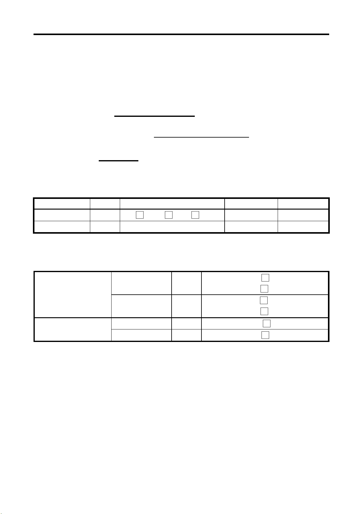
SPECIFICATIONS
Model NO:
Serial NO:
Production Date:
Control:Volt
Drive specifications:
Drive Motor Q’ty HP Volt Hz
Saw arbor 1 □7.5 □10 □15
Feed 1 2
Belt specifications:
7.5、10 HP 5 pcs Triangular belt □A-52(50Hz)
□A-58(60Hz)
Saw motor
15 HP 3 pcs Triangular belt □3V-530(50Hz)
□3V-600(60Hz)
variable speed 1 pcs ribblt belt □1922V-386
Conveyor belt
accelerator
5-step speed 1pcs Triangular belt □SPZ-1037
C12RSH
0733030
DEC.2007
110
✔
230
230
60
60
✔
✔

SRS-12HMANUAL PREFACE
PREFACE
This manual explains how to install, operate, and maintain the
STRAIGHT LINE RIP SAW. Please make certain to read the information
contained herein to ensure safe operation and to achieve the longest lifespan and
finest results possible.
When your saw requires professional repair or maintenance, contact your local
dealer geving him the following information:
;Model number
;Serial number
;Date of purchase
;Precise details of the fault or problem
Your dealer can provide parts and service authorized by head office ensuring safe and
efficient operation.
A list of addresses and telephone numbers of dealers worldwide can be found in the
appendix at the back of this manual.
IMPORTANT!
By reason of safety, the operator MUST
wear leather gloves and leather apron
C12RSH

SRS-12H MANUAL CONTENTS
CONTENTS
CHAPTER 1: INTRODUCTION ...........................................1
1-1 SPECIFICATIONS TABLE ......................................1
1-2 FEATURES..............................................................2
1-3 LOCATION OF PARTS ...........................................4
CHAPTER 2: INSTALLATION .......................... 8
2-1 PRE-INSTALLATION INSPECTION ............. 8
2-2 MOVING THE MACHINE ...................... 8
2-3 FIX THE MACHINE IN POSITION .............. 9
2-4 POWER CONNECTION ....................... 9
2-5 START-UP TEST ............................. 9
2-6 CONNECTION OF DUST COLLECTION
APPARATUS ................................. 11
CHAPTER 3: OPERATION...................................................12
3-1 INSTALLING AND REMOVING BLADE..................12
3-2 CHECKING SAFETY DEVICES..............................14
3-3 RAISE/LOWER PRESSURE ROLLER ASSEMBLY15
3-4 START SAW BLADE...............................................15
3-5 START FEED CHAIN..............................................16
3-6 ADJUSTING THE POSITION OF RIP FENCE........18
3-7 FEEDING .................................... 18
CHAPTER 4: SAFETY PRECAUTIONS ................. 19
CHAPTER 5: MAINTENANCE & REPLACEMENT...............24
5-1 CLEANING ..............................................................24
5-2 LUBRICATION.........................................................25
5-3 ADJUST AND REPLACE SAW ARBOR BELT .......27
5-4 INSPECT AND REPLACE THE VARIABLE SPEED
BELT.......................................................................28
5-5 ADJUST THE OIL SUPPLY TO FEED CHAIN........29
5-6 WEEKLY CLEANUP................................................31


SRS-12H MANUAL Chapter 1: Introduction
1
CHAPTER 1: INTRODUCTION
1-1 SPECIFICATIONS TABLE
Mini. length of workpiece 200 mm
Max. cutting thickness 85 mm
Distance between saw and column 460 mm
Saw arbor motor 7.5,10 or 15 HP
Saw arbor speed 4500 R.P.M.
Saw blade diameter ∅200-∅300 mm(8”-12”)
Saw blade bore ∅25.4 mm
Feed motor 2 HP
Feed speed Variable speed 17 ~ 40 M/min
5-Step speed 18、22、28、34、42 M/min
Number of holding rollers 8 pcs
Dust hole diameter ∅100 mm
Work table height (H) 800 mm
Table area(W×L) 1000×1450 mm
Overall dimension (W×L×H) 1200×1720×1560 mm
Shipping dimension (W×L×H) 1400×1650×1510 mm
Net weight 950 kgs
Shipping weight 1150 kgs
zWe reserve the right to amend any of the above specifications without prior notice.

SRS-12H MANUAL Chapter 1: Introduction
2
1-2 FEATURES
PRECISION-PROCESSED FEED CHAIN AND GUIDE TRACK
The feed chain block and guide track are made of special cast iron. The high-
grade steel connecting pin are heat-treated and ground for maximum durability.
EIGHT PRESSURE ROLLERS HOLD THE WORKPIECE
STABLY
Eight pressure rollers arranged in six rows on both sides, the front and rear of
sawblade and supported by hinges so that they are smooth and stable in motion.
PRECISION-BUILT SAW ARBOR MOUNTING
Made of nickel-chrome steel, through heat-treated, accurately ground and
dynamically balanced, it runs on precision angular-contact ball bearings which
eliminate any radial run-out and axial thrust at high speed of 4500 r.p.m. and
then ensure accuracy of sawblade and workpiece profile.
POWERFUL ARBOR DRIVE MOTOR
Saw arbor is driven with a motor by means of V-belts. There are 3 choices on
saw motor: 7.5HP, 10HP or 15HP, depending on work requirement.
VARIABLE FEEDING SPEEDS
The feeding speed can be adjusted variably at any speed between 17~40 Meter
per minute, easy to operate.
RIGID CABINET CONSTRUCTION
Cabinet machine base is welded with steel plate. The rigid structure ensures
the strength and stability of the machine.
MOVABLE AND FIXED ANTI-KICKBACK FINGERS
The unique design of auto-adjust anti-kickback fingers to be installed between
the first and the second rollers. This anti-kickback fingers will always retain
at the most safe position while raising or lowering pressure rollers. The
operators need not to adjust the fingers. Also, the first row of upper anti-
kickback fingers is independently mounted on an overarm hanger, and one row
of bottom anti-kickback fingers is fitted in front of feed chain.
These three rows of anti-kickback fingers and lateral safety guard prevent the
operator from the dangers of workpiece kickback, ensure the operator’s safety
completely.

SRS-12H MANUAL Chapter 1: Introduction
3
SELF LUBRICATION
The central lubrication system ensures a permanent oil film between feed chain
and guide track. If the oil in tank is below the safety level, the warning lamp
will light up and the feed chain will stop running automatically. This fully
ensures the service life of the feed chain and track.
SRS-12H MANUAL Chapter 1: Introduction
4
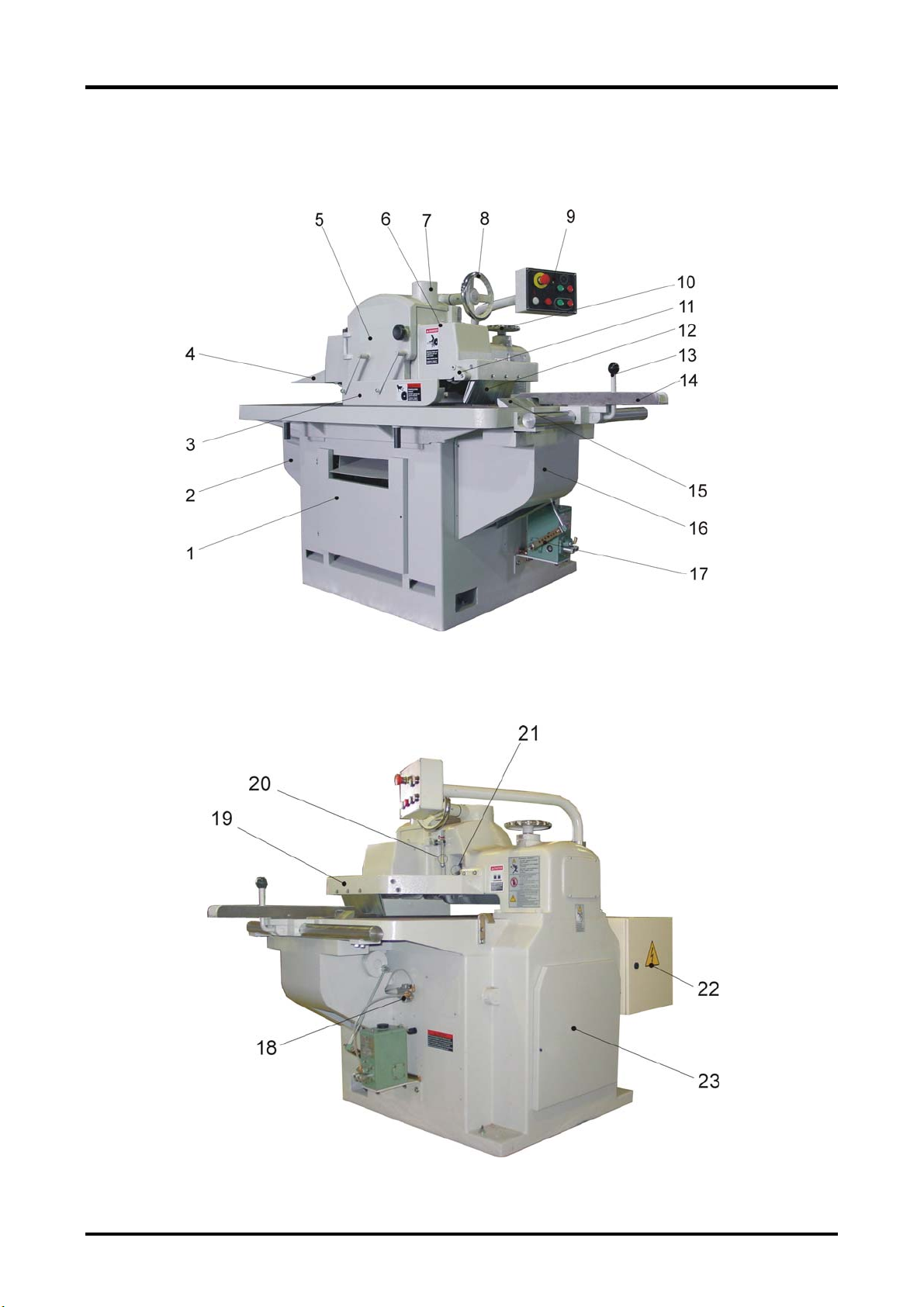
1-3 LOCATION OF PARTS

SRS-12H MANUAL Chapter 1: Introduction
5
1. Feed chain cover
2. Driving sprocket cover
3. Lateral safety guard
4. Outfeed safety plate
5. Saw arbor cover
6. Pressure roller housing
7. Dust suction outlet
8. Pressure roller height-adjustment Hand wheel
9. Control panel
10. Saw arbor height-adjustment hand wheel
11. Anti-kickback finger operation handle
12. First row of upper anti-kickback fingers
13. Fence clamp handle
14. Rip fence
15. Lower anti-kick fingers
16. Driven sprocket cover
17. Mechanical lubricator
18. Oil distributor
19. Anti-kick finger bracket
20. Pressure roller locking lever
21. Saw arbor locking lever
22. Electric box
23. Arbor pulley cover
Table des matières


