CAMELBACK Displays Practico FPZ-640 Mode d’emploi

Model: FPZ-640
Installation and Assembly:
Practico Flat Panel Stand for up to 42" Screens
Max Load Capacity: 110 lb (49kg)

Security Fasteners
M4 x 12 mm (4)
(510-1079)
M4 x 25 mm (4)
(510-1082)
M5 x 12 mm (4)
(520-1064)
M6 x 30 mm (4)
(520-1067)
M6 x 12 mm (4)
(520-1050)
M6 x 25 mm (4)
(520-1211)
M6 x 20 mm (4)
(520-9554)
M5 x 25 mm (4)
(520-1122)
.048" washer (4)
(540-1040)
.5" spacer (4)
(540-1058)
Tools Needed for Assembly
• 1/2" wrench
A
B
C
• Do not begin to install your product until you have read and understood the instructions and warnings contained in
this Installation Sheet. If you have any questions regarding any of the instructions or warnings, for US customers
please call Peerless customer care at 1-800-865-2112, for all international customers, please contact your local
distributor.
• This product should only be installed by someone of good mechanical aptitude, has experience with basic building
construction, and fully understands these instructions.
• Never exceed the Maximum Load Capacity. See page one.
• Always use an assistant or mechanical lifting equipment to safely lift and position equipment.
• Tighten screws firmly, but do not overtighten. Overtightening can damage the items, greatly reducing their holding
power.
• This product is intended for indoor use only. Use of this product outdoors could lead to product failure and personal
injury.
WARNING
Parts List
Description Qty. Part #
Aadjustable column 1 201-1727
Bstand base 1 201-1717
Callen wrench 1 560-1129

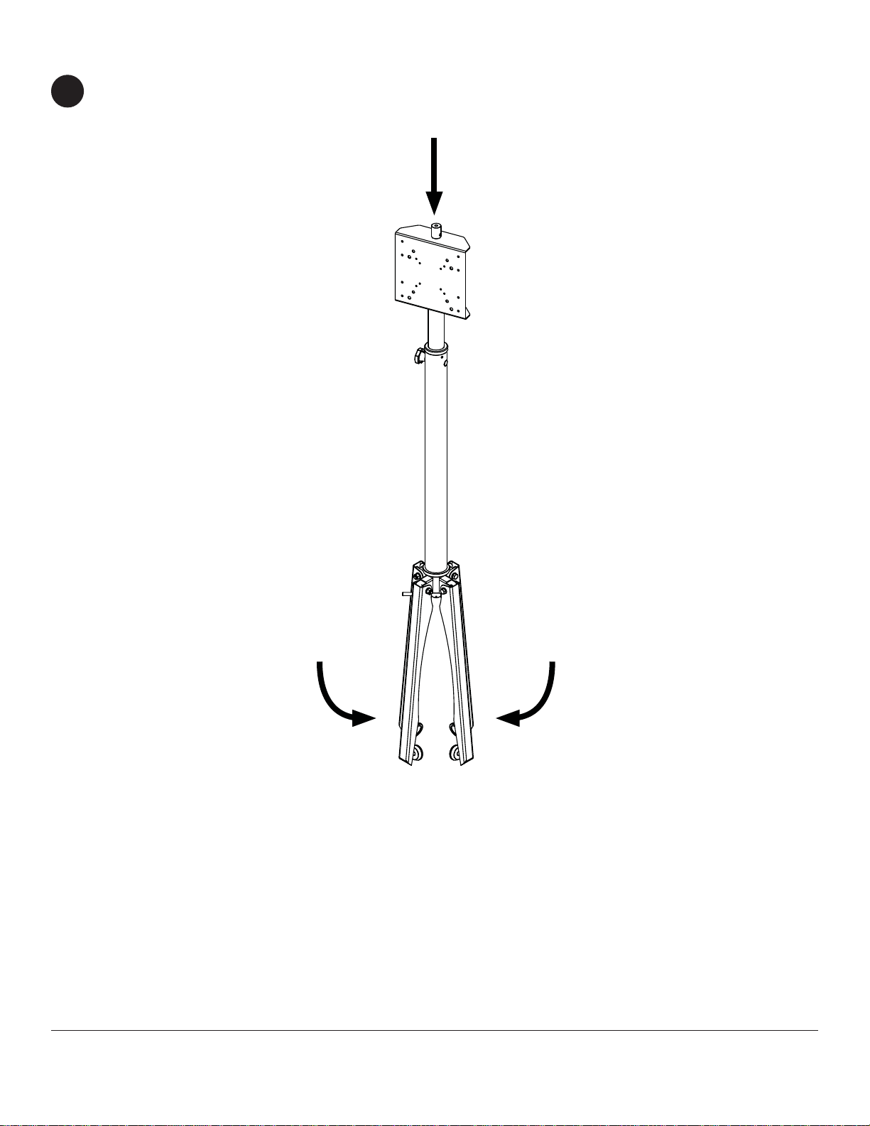
1Open the four legs of stand base (B).
2Place adjustable column (A) on stand base (B).
Make sure the rod of stand base (B) aligns with the
hole of adjustable column (A).
Turn handle of stand base (B) to secure it to
adjustable column (A).
3
BB
B
A
rod
hole

Select security screw that best fits your screen. Center adapter plate of column (A) on the back of the screen and
align the four mounting holes. Attach column (A) to screen with four screws and four washers using allen wrench
(C) as shown in figure 5.1. If screen has a bumped out or recessed back, spacers may be used between the screen
and adapter plate of column (A) as shown in figure 5.2. Screw must make at least three full turns into mounting
hole and fit snug into place.
4
Remove Adapter Plate from Adjustable Column
Remove screw and washer from top of adjustable column (A) using a 1/2" socket wrench as shown in figure 4.1.
Remove hex nut and bolt from back of adapter plate. Slide adapter plate of adjustable column (A) off as shown in
figure 4.2.
A
5
Mounting and Removing Flat Panel Screen
screw
washer
screen
Figure 5.1 Figure 5.2
spacer
screw
washer
screen
adapter plate
Figure 4.1 Figure 4.2
adapter plate adapter plate

Loosen adjustment knob and remove bolt. Adjust
column to desired height. Insert bolt back into
column (A) and tighten adjustment knob.
Cords may be routed through column (A) as shown.
7 8
Height Adjustment Cord Management
adjustment knob
bolt
A
Slide adapter plate onto adjustable column (A) as shown in figure 6.1. Reinstall nut and bolt on back of adapter
plate using a 1/2" socket wrench as shown in figure 6.2. Reinstall screw and washer on top of adjustable column
(A).
6
Place Adapter Plate on Adjustable Column
Figure 6.1 Figure 6.2
Adjust column (A) to its lowest height as shown in step seven. Close the four legs of stand base (B).
Collapsing the Stand
9

Instalación y montaje:
Practico Monitor Plano de Pantalla Plana de 42"
Modelo: FPZ-640 Máxima capacidad de carga: 110 lb (49 kg)

Español
Lista de piezas
Descripción Cant. Nº de pieza
Acolumna 1 201-1727
Bsoporte 1 201-1717
Cllave allen 1 560-1129
Tornillos de Seguridad
M4 x 12 mm (4)
(510-1079)
M4 x 25 mm (4)
(510-1082)
M5 x 12 mm (4)
(520-1064)
M6 x 30 mm (4)
(520-1067)
M6 x 12 mm (4)
(520-1050)
M6 x 25 mm (4)
(520-1211)
M6 x 20 mm (4)
(520-9554)
M5 x 25 mm (4)
(520-1122)
.5" espaciador (4)
(540-1058) .048" arandela múltiple(4)
(540-1040)
Herramientas necesarias para el ensamblaje
•llave inglesa 1/2"
• No comience a instalar su producto hasta haber leído y entendido las instrucciones y las advertencias contenidas
en la Hoja de Instalación. Si tiene alguna pregunta acerca de cualquiera de las instrucciones o las advertencias, por
favor, llame a Servicio al Cliente de Peerless al 1-800-865-2112 si está en EE. UU. Si es un cliente internacional, por
favor, comuníquese con su distribuidor local.
• Este producto sólo debe ser instalado por una persona que tenga una buena aptitud mecánica, que tenga experien-
cia en construcción básica de edificios y que entienda estas instrucciones en su totalidad.
• Nunca sobrepase la capacidad máxima de soportar carga. Vea la página 6.
• Siempre cuente con la ayuda de un asistente o utilice un equipo mecánico de izar para levantar y colocar el equipo
con más seguridad.
• Apriete los tornillos con firmeza, pero no en exceso. Apretarlos en exceso puede dañar los artículos y puede disminu-
ir significativamente su fuerza de fijación.
• Este producto está diseñado para uso en interiores solamente. Utilizar este producto en exteriores podría causar fal-
las del producto y lesiones a individuos.
ADVERTENCIA
A
B
C

Español
1Abrir las cuatro patas de soporte (B).
Coloque la columna ajustable (A) en la base
de soporte (B). Asegúrese de que la vara de la
base del soporte (B) se alinea con el orificio de la
columna ajustable (A).
Gire el mango de soporte (B) para asegurar que la
columna (A).
2 3
BB
B
A
vara
orificio

Español
Seleccione el tornillo de seguridad que mejor se adapte a tu pantalla. Centro de soporte de adaptador de la
columna (A) en la parte posterior de la pantalla y alinee los cuatro agujeros de montaje. Coloque la columna (A)
a la pantalla con cuatro tornillos y cuatro arandelas con una llave allen (C) como se muestra en la figura 5.1. Si
la pantalla tiene un golpeado o empotrada posterior puede utilizar espaciadores entre la pantalla y el soporte
adaptador de la columna (A) como se muestra en la figura 5.2. El tornillo debe dar por lo menos tres vueltas
completas en el agujero de instalación y debe quedar ajustado en su lugar.
5
Instalación y desinstalación de la pantalla plana
tornillo
arandela
pantalla
Figura 5.1 Figura 5.2
espaciadores
tornillo
arandela
pantalla
4
Retirar la Placa Adaptadora de la Columna Ajustable
Quite el tornillo y la arandela de la parte superior de la columna ajustable (A) con una 1/2" llave como se muestra
en la figura 4.1. Quite la tuerca hexagonal y el tornillo de la parte posterior de la placa adaptadora. Placa
adaptadora de diapositivas de la columna ajustable (A) de la manera ilustrada en la figura 4.2 .
A
Placa
Adaptadora
Figura 4.1 Figura 4.2
Placa
Adaptadora Placa
Adaptadora
Table des matières
Langues :
Autres manuels CAMELBACK Displays Support et étagère

Manuels Support et étagère populaires d'autres marques

Salamander
Salamander Acadia AC/W/L400/WH Manuel utilisateur

Fohhn
Fohhn VAT-09 Guide de l'utilisateur

ricoo
ricoo FS0522 Manuel utilisateur

AMSOIL
AMSOIL BMK-22 Guide rapide

Kargo Master
Kargo Master 48220 Manuel utilisateur

Milestone AV Technologies
Milestone AV Technologies SIMPLICITY SLF2 Manuel utilisateur


