Cablematic KV01 Manuel utilisateur

8 / 16 port combo KVM Switch
1+1 Console 8 / 16 port combo KVM Switch
User Manual
V2.0
2008.2.19

1+1 Console Combo KVM Switch
2 / 19
C o n t e n t s
1.Introduction............................................................................................................................... 4
1.1Back Panel........................................................................................................................... 4
1.2Main Features...................................................................................................................... 5
1.3Package Contents................................................................................................................ 6
1.4System Requirements.......................................................................................................... 6
1.5Cables Diagrams................................................................................................................. 6
1.5.13-in-1 DB15 Cable.......................................................................................................6
1.5.2PS/2 (keyboard) to USB adapter..................................................................................6
1.5.3Daisy Chain Cable .......................................................................................................7
1.5.4CAT. 5 / 5E / 6 Straight Through UTP / STP Cable.....................................................7
2.Hardware Installation............................................................................................................... 8
2.1Rack Mount Installation...................................................................................................... 8
2.2Computer / Server Installation............................................................................................ 9
2.2.13-in-1 HDB15 Cable Installation.................................................................................9
2.3Console Installation .......................................................................................................... 10
2.3.1Local Console ............................................................................................................10
2.4Optional Modules Installation............................................................................................11
2.4.1IP Module...................................................................................................................11
2.4.2CAT. 5 Transmitter Module .......................................................................................11
2.5Power ON.......................................................................................................................... 12
2.6CAT. 5 KVM Receiver (R-Box) ....................................................................................... 12
2.7CAT. 5 Receiver Installation............................................................................................. 12
2.8When video signal is foggy or unclear ............................................................................. 13
2.9Daisy Chain Connection ................................................................................................... 13
3.Usage ........................................................................................................................................ 14
3.1Hotkey Commands and OSD Operations ......................................................................... 14
3.2Sun and MAC Function Key Mapping............................................................................. 15
3.3Buttons.............................................................................................................................. 15
3.4Front Panel -- Port LED Indications ................................................................................. 16
3.5BANK 7-seg LED............................................................................................................. 16
3.6Hot Plug ............................................................................................................................ 16
4.Technical Specifications ......................................................................................................... 17
5.Troubleshooting....................................................................................................................... 18
6.Certifications ........................................................................................................................... 19

1+1 Console Combo KVM Switch
3 / 19
F i g u r e s
Figure 1. Back Panel....................................................................................................................... 5
Figure 2. 3-in-1 DB15 Cable.......................................................................................................... 6
Figure 3. PS/2 keyboard to USB adapter ....................................................................................... 7
Figure 4. Daisy Chain Cable .......................................................................................................... 7
Figure 5. CAT5/5E/6 Straight Through UTP/STP Cable (8P8C)................................................... 7
Figure 6. Rack Mount Installation.................................................................................................. 8
Figure 7. Footpads Installation....................................................................................................... 8
Figure 8. Computer/Server Installation.......................................................................................... 9
Figure 9. 3-in-1 DB15 cable........................................................................................................... 9
Figure 10. 3-in-1 DB15 Cable and PS/2 to USB Adaptor.......................................................... 10
Figure 11. Local Console Installation ........................................................................................ 10
Figure 12. IP-Module ..................................................................................................................11
Figure 13. Connect to CAT5 Receiver (R-Box)......................................................................... 12
Figure 14. Daisy Chain Connection ........................................................................................... 13
Figure 15. Daisy Chain through Computer Port......................................................................... 14
Figure 16. Front Panel................................................................................................................ 16

1+1 Console Combo KVM Switch
4 / 19
1. Introduction
The 1+1 Console 8/16 port KVM switch can control attaching servers and computers from local or
remote console. This KVM switch is loaded with features such as one local console port, plus one
optional CAT. 5-based remote console port or one optional IP-based remote console Port, On
Screen Display (OSD) Menu, Password security, Hot key Control, Push Button and Auto Scan
Control. It has complete keyboard and mouse emulation for simultaneous PCs boot-up process.
With the CAT.5-based remote console port you can you remotely control servers and computers
1000 feet away. In other words, you can locate your monitor, keyboard and mouse up to 1000 feet
away from the KVM switch. The built-in CAT.5 transmitter synthesizes VGA monitor and
keyboard/mouse signals, and transmit the signals to the remote CAT.5 receiver over the popular
LAN CAT.5 cable.
With the IP-based remote console port you can control one or many computers locally at the server
site or remotely via the Internet using a standard browser. You can securely gain BIOS level access
to systems for maintenance, support or failure recovery over the Internet. Communication is secure
via SSL encryption.
1.1 Back Panel
8 port combo PS/2 console KVM Switch
16 port combo PS/2 console KVM Switch
1+1 Console, 8 port combo PS/2 console KVM switch
1+1 Console, 16 port combo PS/2 console KVM switch with CAT5 extender module

1+1 Console Combo KVM Switch
5 / 19
1+1 Console, 16 port combo PS/2 console KVM switch
1+1 Console, 16 port combo USB console KVM switch with CAT5 extender module
Figure 1. Back Panel
The 1+1 console is designed as one control two views, both local console and remote console can
access and view the same computer port, but only one console control at a time. These two consoles
are operating on first come first served basis. If the controlling console does not have keyboard or
mouse activity for 2 seconds, the other console may take over the control right.
1.2 Main Features
Support combo interface for connecting to computer ports conveniently
Support one local console and one optional remote console (CAT.5 or over IP)
CAT.5 console up to 1000 feet away from KVM switch with superior auto-adjust RGB
gain/delay control capability
Support MS windows, Netware, Unix and Linux with PS/2 port
Support iMAC, Power MAC and Sun Micro Systems with USB port
No Software Required --- easy computer selection via On Screen Display (OSD) Menu, Push
Buttons, and Hotkeys
Provide various Hotkey (Scroll-Lock/ Cap-Lock/ Num-Lock/ L-Alt/ L-Ctrl/ L-Win/ R-Alt/
R-Ctrl/ R-Win) for switching computer port and other control functions, so Hotkey function
can be used in various types of keyboards, and to avoid Hotkey duplicate problem.
Provide ACL (Access Control List) security function. Store up to 8 independent user accounts
Hot Plug --- add or remove connected computers without powering off the KVM switch or
computers
Support two user layers, and search computer/server name
Plug-n-Play monitor support
Keyboard status restored when switching computer
Support Daisy Chain function with both Bus (8-layer) and Tree (2-layer) topologies

1+1 Console Combo KVM Switch
6 / 19
1.3 Package Contents
1x KVM Switch Unit
1x CD-ROM (User manual, QSG)
1x AC to DC Power Adapter
1x Rack Mount Kit
1x Footpads set
1.4 System Requirements
Combo KVM Host side HDDB15 male to one HDDB15 male and two
mini din 6-pin PS/2 connectors
Local Console side
(USB console)
■One VGA Monitor
■One USB Keyboard
■One USB Mouse
Local Console side
(PS/2 console)
■One VGA Monitor
■One PS/2 Keyboard
■One PS/2 Mouse
IP Console module ■One CAT.5 cable
■Network access environment
CAT.5 KVM extender
module
■One CAT.5 cable
■R-Box (CAT.5 KVM extender receiver)
■One VGA Monitor
■One USB Keyboard
■One USB Mouse
■Optional computer
USB to PS/2 Adapter Optional for computer without PS/2 ports
1.5 Cables Diagrams
1.5.1 3-in-1 DB15 Cable
HDDB15 male to one HDDB15 male and two mini din 6-pin PS/2 connectors.
Figure 2. 3-in-1 DB15 Cable
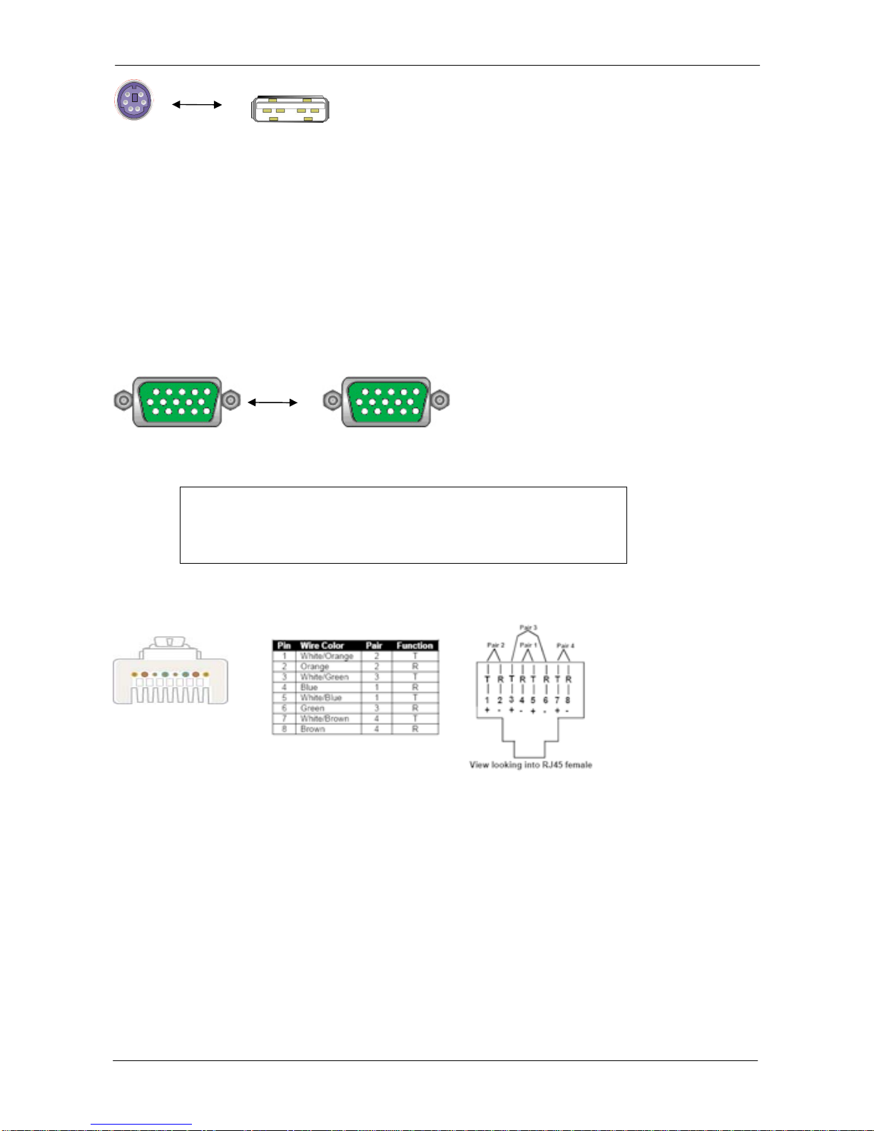
1.5.2 PS/2 (keyboard) to USB adapter
PS/2 (keyboard) to USB (keyboard and mouse) adapter.
1+1 Console Combo KVM Switch
7 / 19
Figure 3. PS/2 keyboard to USB adapter
1.5.3 Daisy Chain Cable
VGA Cable: HDDB15 Male to Male
Figure 4. Daisy Chain Cable
Note:
Daisy chain needs the cable all 15 lines connected. This is a special
VGA cable, normal VGAcable has unconnected lines. Do not use
other VGA cable for daisy chain.
1.5.4 CAT. 5 / 5E / 6 Straight Through UTP/ STP Cable
Figure 5. CAT. 5 / 5E / 6 Straight Through UTP/ STP Cable (8P8C)

1+1 Console Combo KVM Switch
8 / 19
2. Hardware Installation
Before installation, please make sure all of peripherals and computers have been turned off.
2.1 Rack Mount Installation
Find a convenient place to put your KVM Switch. The 19” rack mount form factor makes it ideally
mountable on a 19” rack. When mounting to a rack, attach the included brackets to the sides of the
KVM Switch. Take note of the length of your cables so that your computers, KVM Switch,
keyboard, mouse and monitor are distanced properly.
Figure 6. Rack Mount Installation
The KVM Switch can also be placed on a desk with attached footpads. To install footpads, please
turn upside down; and refer to the following instructions properly for installing the footpads.
Figure 7. Footpads Installation

1+1 Console Combo KVM Switch
9 / 19
2.2 Computer / Server Installation
Figure 8. Computer/Server Installation
2.2.1 3-in-1 HDB15 Cable Installation
On the back of the KVM Switch, each of the 8 /16 PC ports has a HDB15 type connector. Each
cable that comes with the Switch has a 3-in-1 connector at one end and a single HDB15 male
connector at the other end. Plug the single connector end of the cable into the KVM PC port, and
then plug the other end of cable to a PC VGAport.
Figure 9. 3-in-1 DB15 cable
Figure 10.

1+1 Console Combo KVM Switch
10 / 19
(a) PS/2 computer --- Plug in the PS/2 mouse connector to the computer mouse port, then the PS/2
keyboard connector to computer keyboard port.
Figure 11.3-in-1 DB15 Cable and PS/2 to USB Adaptor
(b) USB computer --- Install a PS/2-to-USB adapter to the keyboard PS/2 connector, plug in USB
connector to the PC USB port. This single USB port can handle both keyboard and mouse data.
2.3 Console Installation
2.3.1 Local Console
Connect the monitor to the HDB15 female port on the back of the KVM unit labeled with the
monitor symbol at the Local Console connector.
There may be USB local console or PS/2 local console. For USB local console, connect the USB
keyboard to either one of USB local port and USB mouse to the other USB port. These USB ports
are special designed for keyboard and mouse, and can not work with USB hub or other USB
devices. For PS/2 local console, connect keyboard to purple PS/2 port and mouse to green PS/2
mouse port. There is a Daisy chain port under VGA ports.
Figure 12.Local Console Installation
Table des matières
Manuels Routeur réseau populaires d'autres marques


NETGEAR
NETGEAR FS526T - Switch Manuel utilisateur

Korenix
Korenix JetNet 5710G Series Manuel utilisateur

Automated Logic
Automated Logic ZN551 Manuel du propriétaire

Cisco
Cisco ASR 1000 Series Manuel de l'opérateur

EnGenius
EnGenius ESR-9710 Manuel utilisateur

Cisco
Cisco 805 Series Instructions d'utilisation et de sécurité