C.S.L. VARIVAC 2006 B Manuel utilisateur

1

2
Varivac™ Installation Manual
Contents
1. General Information
2. Varivac Mounting and wiring
3. Transducer Mounting and wiring
4. Set up and Automatic Motor Tuning
(AMA)
5. Vacuum Level Adjustment
6. Idle Speed Adjustment
7. Common Errors
8. Terms & Conditions
9. Internal wiring diagram
1. General Information
Varivac is a protected Trademark belonging to Corkill Systems Limited, unauthorised use
of this name will lead to prosecution.
Varivac is available in standard motor sizes from 4 kilowatts to 30 kilowatts, model
CSLV4 has a 4 kilowatt capacity, CSLV5.5 is 5.5 kilowatt, etc. The suffix “T” refers to a
Tandem Varivac, this model controls two motors simultaneously and has individual
motor circuit-breakers inside to protect the motors. The Varivac should be sized for the
combined rating of the motors, for example, 1 x 11kw + 1 x 7.5kw motor = 18.5kw,
therefore the model Varivac should be CSLV18.5T. Twin pump set ups are discouraged
where for example the larger vacuum pump is controlled by a Varivac and the second
pump is “called” as required. This system is cheaper to purchase but leads to problems as
the primary pump wears and the second pump is called more frequently causing a “blip”
in the vacuum as the pump comes in and is switched off again. Tandem pump systems
have been documented to be more economic to run even with two motors running plus
the total reserve in the combined motors is instantly available when required.
All enclosures are rugged Stainless Steel, be wary of mounting the Varivac in such a way
that the thermostatic controlled booster fan will not draw in moisture or steam when it

3
starts. Although all Varivacs have booster fans fitted, cooling is very rarely an issue and
covers are available to blank the fan off if moisture is the greater problem.

4
CABLING AND MOTOR
The Varivac is designed to be permanently wired on a dedicated circuit with protection
according to the controller Specification sheet current ratings. Cables to the electric
motor must be screened, minimum size 4 X 2.5mm, CBS type preferred. The Cable
between the Varivac and transducer is to be of minimum 0.2mm 2 core screened and not
to be run parallel with heavy current carrying cables. Belden type cable is preferred and is
supplied with the Varivac.
The power supply cable to the drive can be non screened TPS or similar
A Mains and RF filter is factory fitted internally in all controllers, this is normally
adequate however we recognize there are certain areas within NZ where this filter will
not be sufficient to suppress all radio interference, please contact us for more information
if this is the case.
In suspect poor power areas, should the incoming voltage drop below the unit tolerance
levels, the unit will trip on error 13. This requires a complete shut down and restart.
The client should talk to their electrician or network supplier if this condition persists as
the Electrical Regulations state minimum mains supply voltage levels. This requirement
is well above the controller Low Voltage tolerance level, please note that this low voltage
condition will not damage the controller but could damage other electrical apparatus.
The voltage tolerance level with three phase controllers is 380 volts.

5
2. Mounting and Wiring
Single Pump & Motor Combination
This system consists of one motor with one or more vacuum pumps attached.
1. Generally mount the Varivac adjacent the vacuum pump.
2. Re-use the existing isolator normally at this point.
3. Remove power factor capacitor if connected (Varivac does this function).
4. Remove motor cable from the motor and re-terminate into the Varivac supply
terminals L1, L2 & L3. Connect the Earth to the screw/terminal provided.
5. Fit a new cable (screened cable preferred) from the Varivac to the motor.
6. If the starter is at the switchboard, remove the overload and continue using this starter
to start the Varivac and any auxiliary equipment.
7. If the starter is adjacent the pump, remove completely and switch any Auxiliary
equipment via the relay provided in the Varivac (not more than 5 amps!)
8. If a Star/Delta Starter is being replaced, connect motor in Delta
– check the motor name plate for correct configuration!

6
Tandem Pump & Motor Combination
This system consist generally of two motors wired separately each with one or more
vacuum pumps attached. These motors may be of different sizes, this does not matter !
1. Generally mount the Varivac adjacent the switchboard.
2. Re-use the existing isolators normally by the motors.
3. Remove power factor capacitors if connected (Varivac does this function).
4. Connect a new cable from a circuit-breaker or fuses sized to handle the combined
vacuum pump motors full load current to the Varivac.
5. Either replace the motor cables with screened cables (this may not always be practical)
or re-route and connect the existing motor cables to the Motor Circuit-breakers in the
Varivac. Set the correct motor currents on the overloads in the Varivac enclosure.
6. If the starters at the switchboard are used to control auxiliary equipment, connect these
to the auxiliary relay in the Varivac, Terminals #6 & #7 – not more than 5 amps please !
7. If the starters are adjacent the pump, remove completely and connect to the isolators.
8. If Star/Delta Starters are being replaced, connect motors in 400 volt configuration,
Delta on 400/600v motors and Star on 230/400v motors – check the motor name plate.
7
Twin Pump & Motor Combination
This system is not normally used unless the plant has a huge vacuum over-capacity, it
consists generally of two motors wired separately each with one or more vacuum pumps
attached. These motors may be of different sizes, this does not matter!
1. Generally mount the Varivac adjacent the switchboard.
2. Re-use the existing isolators normally by the motors.
3. Remove power factor capacitors if connected (Varivac does this function).
4. The largest motor is connected via the Varivac.
5. Either replace the motor cable with screened cables (this may not always be practical)
or re-route and connect the existing motor cable to the Varivac.
6. If the starter at the switchboard is used to control auxiliary equipment, remove the
overload and use this contactor to start the Varivac, Terminals #6 & #7 in the Varivac
should be used to start the secondary pump contactor or soft starter (a soft starter is
highly recommended for this system).
7. If the starters are adjacent the pumps, mount the Varivac in the place of the largest
motor starter and connect the second starter to the Varivac.
8. If a Star/Delta Starter is being replaced, connect the motor in 400v configuration
– check the motor name plate!
9. A check valve will need to be fitted to the secondary pump inlet side to stop air being
pulled into the system via the vacuum pump exhaust when this pump is on standby.

8
3. Transducer Installation
General; mount the transducer as close to the action as possible, the sensing face is
VERY sensitive and easily damaged, be very careful with it.
Only mount the transducer in the Vacuum Interceptor when no other option is practical –
it will still work well but in high vacuum loss situations the vacuum at the cups will be
lower than at the transducer sensing face due to friction losses in the plant pipe work.
Herringbone Dairy – mount in the Hygienic Can as first choice or Milk Receiver as
second choice. The Hygienic can be drilled and a standard mounting kit used or insert in
the Milk Receiver, this will require the tri-clover fitting welded in (see photo) and creates
a point that must be cleaned periodically and therefore provides a risk of damaging the
transducer.

9
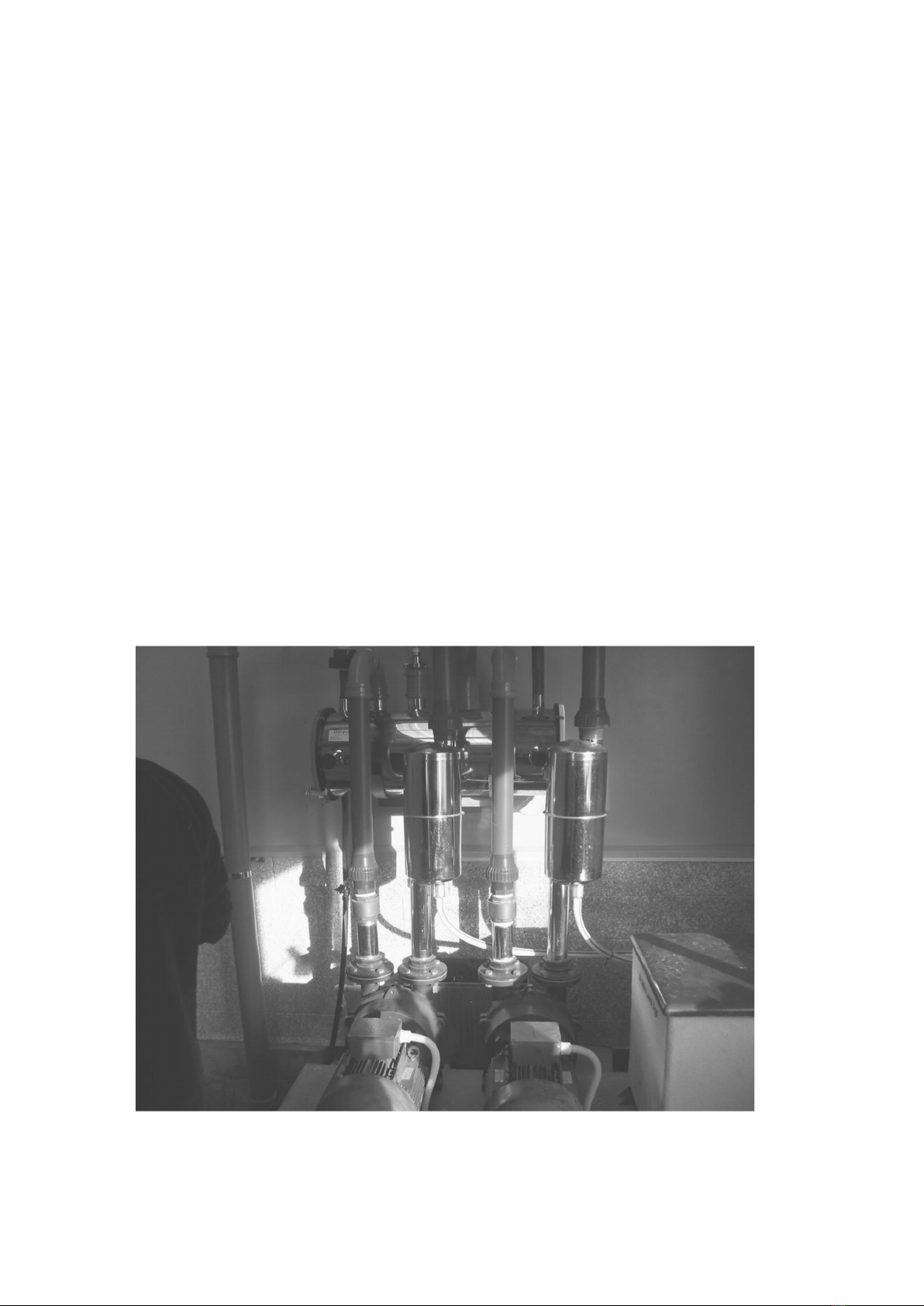
Rotary Dairy – mount as close as possible to the gland, in the installation photos below
the tee moves the transducer out of direct air flow – this is good. There is often a spare
outlet in the gland this is a good point to mount the transducer – beware of the transducer
being accidentally knocked by operators or moving pipe work. If possible always mount
the transducer upright to protect against moisture ingress.
Protect the transducer Belden cable through
the duct with conduit or flexi-conduit
vibration can crush the cable or rodents
may chew it
Connections:
Single pair screened belden cable is supplied with the Varivac, connect the white to
terminal #1 at both Transducer and Varivac and Black to terminal #2 with the drain wire
connected to Earth at both ends
Avoid running the transducer cable parallel with high current and/or voltage cables as
interference can be induced into the cable.

10
Do not mount the transducer ever like the following picture
This is Very Bad !!!! – all kinds of stability problems !!! – too close to the vacuum
pump and welded directly into a very small main air line.
Ce manuel convient aux modèles suivants
1


