BridgeTech VB20 Manuel utilisateur

VB2-series
Users' Manual
Sw version 5.0
The current manual is always found in the lo -in area of the www.brid etech.tv site.
Refer to section 1.2 of this manual for more information.
PROBE USERS' MANUAL VERSION 5.0
2014© BRIDGE Technolo ies Co AS - Bentsebru ata 20 - N-0476 Oslo, Norway - tel: +47 22 38 51 00 -
www.brid etech.tv

Table of Contents
1 INTRODUCTION..............................................................................................................7
1.1 About the Probe...........................................................................................................7
1.1.1 Probe - Overview.................................................................................................7
1.1.2 VB20 an VB220...................................................................................................8
1.1.3 Probe - Functionality............................................................................................9
1.2 How to use this manual...............................................................................................10
2 PRINCIPLE OF OPERATION.........................................................................................11
3 SAFETY......................................................................................................................... 13
4 INSTALLATION AND INITIAL SETUP.............................................................................14
4.1 Quick Installation Gui e.............................................................................................14
4.2 The Enhance Chassis (EC)......................................................................................14
4.2.1 Dual Power Supply.............................................................................................15
4.2.2 Cooling System..................................................................................................15
4.3 The Enhance Chassis -48V DC version (ECDC).....................................................16
4.3.1 Dual Power Supply.............................................................................................16
4.3.2 Cooling System..................................................................................................17
4.3.3 ECDC Power Supply...........................................................................................17
4.4 Serial Number Location.............................................................................................18
4.5 Portable chassis (VB20).............................................................................................19
4.5.1 AC Power Supply ...............................................................................................19
4.5.2 Cooling System..................................................................................................19
4.5.3 Serial number location.........................................................................................19
4.5.4 Interfaces............................................................................................................ 19
4.6 The ACC/DCC Har ware (VB220).............................................................................20
4.6.1 Cooling System..................................................................................................20
4.6.2 ACC Power Supply.............................................................................................20
4.6.3 DCC Power Supply............................................................................................21
4.6.4 Serial Number Location......................................................................................21
4.7 The Har ware Mo ules an Connectors (VB220)......................................................22
4.7.1 The Probe Mo ule...............................................................................................22
4.7.2 The VB242 ASI Input Mo ule (VB220 option).....................................................23
4.7.3 The VB250 COFDM Demo ulator Mo ule (VB220 Option)................................24
4.7.4 The VB252 COFDM Dual Demo ulator Mo ule (VB220 Option)........................25
4.7.5 The VB260 QAM Demo ulator Mo ule(VB220 Option)......................................26
4.7.6 The VB262 Dual QAM/8VSB Demo ulator Mo ule (VB220 Option)..................27
4.7.7 The VB270 DVB-S/S2 Demo ulator Mo ule (VB220 Option).............................28
4.7.8 The VB272 ual DVB-S/S2 Demo ulator Mo ule (VB220 Option).....................29
4.7.9 The VB273 DVB-S/S2 Re un ancy switch (VB220 Option)................................30
4.8 Installing the Unit in a Rack (VB220).........................................................................34
4.8.1 Default Installation - Connectors at the Front of Rack........................................34
4.8.2 Optional Installation - Connectors at the Rear of Rack.......................................34
4.8.3 Optional Installation - Mi -Mounting...................................................................35
4.9 Powering up the Unit.................................................................................................35
4.10 Initial Configuration..................................................................................................36
4.10.1 Initial Configuration Using the Pre-Set IP-A ress...........................................36
4.10.2 Initial Configuration Via Serial Console Emulate Over USB...........................36
4.10.3 Verifying Correct Initial Setup of the Probe.......................................................40
4.10.4 Initial Setup Troubleshooting............................................................................41
5 QUICK SETUP GUIDE...................................................................................................42
5.1 Basic Setup: All Interfaces.........................................................................................42
5.2 Input Signal Definitions..............................................................................................42
5.2.1 ASI Input ...........................................................................................................42
5.2.2 Ethernet Input (IP Option Only)..........................................................................42
5.2.3 OTT Input (OTT Engine Option Only).................................................................43
5.2.4 Demo ulator Input(VB220).................................................................................43
5.3 Monitoring: All Interfaces............................................................................................44

5.4 A justing Alarm Threshol s: All Interfaces.................................................................44
6 THE PROBE GRAPHICAL USER INTERFACE..............................................................46
6.1 Main...........................................................................................................................48
6.1.1 Main - Summary.................................................................................................48
6.1.2 Main - CPU usage..............................................................................................52
6.1.3 Main - Eii graphing.............................................................................................53
6.2 Alarms........................................................................................................................54
6.2.1 Alarms - All Alarms.............................................................................................55
6.2.2 Alarms - Alarm setup..........................................................................................56
6.3 OTT (requires the OTT Option)..................................................................................63
6.3.1 Active testing......................................................................................................63
6.3.2 Channels............................................................................................................69
6.3.3 Settings..............................................................................................................71
6.3.4 Threshol s.........................................................................................................72
6.4 Mon ...........................................................................................................................74
6.4.1 Mon - Parameters..............................................................................................74
6.4.2 Mon - Setup.........................................................................................................87
6.5 MW ........................................................................................................................... 87
6.6 RDP........................................................................................................................... 92
6.7 Traffic ........................................................................................................................ 98
6.7.1 Traffic - Protocols (requires AET-OPT)................................................................98
6.7.2 Traffic - Detect...................................................................................................100
6.8 Ethernet ..................................................................................................................101
6.8.1 Ethernet - Summary.........................................................................................101
6.8.2 Ethernet - History.............................................................................................103
6.8.3 Ethernet - IGMP (requires AET-OPT)...............................................................105
6.8.4 Ethernet - Join..................................................................................................106
6.8.5 Ethernet - FSM (requires AET-OPT).................................................................107
6.8.6 Ethernet - Multicasts.........................................................................................110
6.8.7 Ethernet - Ethernet thresh................................................................................114
6.9 ETR 290 (Option).....................................................................................................117
6.9.1 ETR 290 - ETR Overview.................................................................................117
6.9.2 ETR 290 - ETR Details.....................................................................................118
6.9.3 ETR 290 - Services..........................................................................................121
6.9.4 ETR 290 - Bitrates............................................................................................125
6.9.5 ETR 290 - Tables..............................................................................................126
6.9.6 ETR 290 - PID list.............................................................................................128
6.9.7 ETR 290 - PCR................................................................................................129
6.9.8 ETR 290 – T2MI (Option)..................................................................................132
6.9.9 ETR 290 – SCTE 35 (Option)............................................................................134
6.9.10 ETR 290 - Status............................................................................................136
6.9.11 ETR 290 - Compare........................................................................................137
6.9.12 ETR 290 - ETR thresh....................................................................................143
6.9.13 ETR 290 - PID thresh.....................................................................................155
6.9.14 ETR 290 - Service thresh...............................................................................157
6.10 ASI ......................................................................................................................... 160
6.10.1 ASI Status...................................................................................................... 160
6.10.2 ASI - Setup.....................................................................................................162
6.11 ASI (Optional mo ule for VB220)............................................................................164
6.11.1 ASI - Status....................................................................................................165
6.11.2 ASI - Setup (Roun -Robin Mo e)...................................................................166
PROBE USERS' MANUAL VERSION 5.0
2014 © BRIDGE Technolo ies Co AS - Bentsebru ata 20 - N-0476 Oslo, Norway - tel: +47 22 38 51 00 -
www.brid etech.tv
4

6.12 COFDM (VB250 Option Mo ule for VB220)...........................................................167
6.12.1 COFDM - Status (VB250)...............................................................................167
6.12.2 COFDM - Tuning setup (VB250)....................................................................170
6.12.3 COFDM - COFDM threshol (VB250)............................................................173
6.12.4 COFDM - RF Overview (VB250)....................................................................175
6.13 COFDM (VB252 Option Mo ule for VB220)...........................................................176
6.13.1 COFDM - Status (VB252)...............................................................................176
6.13.2 COFDM - Tuning setup (VB252).....................................................................184
6.13.3 COFDM - COFDM threshol (VB252)............................................................187
6.13.4 COFDM - Impulse response (Requires A vance RF Option).......................191
6.13.5 COFDM - RF overview (VB252).....................................................................192
6.14 QAM/VSB/RF (VB260 or VB262 Mo ule Option for VB220)..................................193
6.14.1 QAM - Status..................................................................................................193
6.14.2 QAM - Tuning setup.......................................................................................196
6.14.3 QAM - QAM threshol ....................................................................................199
6.14.4 QAM - RF overview........................................................................................203
6.15 SAT (VB270 or VB272 Option mo ule for VB220).................................................204
6.15.1 SAT - Status...................................................................................................204
6.15.2 SAT - Tuning setup.........................................................................................208
6.15.3 SAT - SAT threshol .......................................................................................211
6.15.4 SAT - RF overview..........................................................................................213
6.16 SAT Re un ancy Switch (VB272 an VB273 Option mo ule for VB220)............214
6.16.1 Tuning setup....................................................................................................214
6.16.2 SAT Tuning setup............................................................................................215
6.16.3 Threshol setup...............................................................................................216
6.16.4 Re un ancy status an overview ...................................................................217
6.16.5 Re un ancy mo es........................................................................................217
6.16.6 Status for input...............................................................................................218
6.17 Setup......................................................................................................................219
6.17.1 Setup - Params..............................................................................................219
6.17.2 Setup - Pages................................................................................................221
6.17.3 Setup - Time...................................................................................................222
6.17.4 Setup - Ethernet.............................................................................................222
6.17.5 Setup - VBC...................................................................................................228
6.17.6 Setup - Login..................................................................................................229
6.17.7 Setup - ETR...................................................................................................230
6.17.8 Setup - VBC thresh........................................................................................234
6.17.9 Setup - Sche uling.........................................................................................236
6.17.10 Setup - Routing............................................................................................238
6.17.11 Setup - Security............................................................................................239
6.18 Data....................................................................................................................... 241
6.18.1 Data - Configuration.......................................................................................241
6.18.2 Data - Software..............................................................................................242
6.18.3 Data - Table Descriptors.................................................................................243
6.18.4 Data - Eii........................................................................................................243
6.18.5 Data - BOOT..................................................................................................245
6.19 About..................................................................................................................... 246
6.19.1 About - Release info.......................................................................................246
6.19.2 About - License..............................................................................................246
6.19.3 About - Technologies......................................................................................247
PROBE USERS' MANUAL VERSION 5.0
2014 © BRIDGE Technolo ies Co AS - Bentsebru ata 20 - N-0476 Oslo, Norway - tel: +47 22 38 51 00 -
www.brid etech.tv
5

1. Appen ix: Probe Versus Vi eoBri ge Controller - Alarms..........................................248
2. Appen ix: Monitoring Practices..................................................................................249
3. Appen ix: OTT Profile Health....................................................................................255
4. Appen ix: Software Uploa ........................................................................................257
PROBE USERS' MANUAL VERSION 5.0
2014 © BRIDGE Technolo ies Co AS - Bentsebru ata 20 - N-0476 Oslo, Norway - tel: +47 22 38 51 00 -
www.brid etech.tv
6

1 INTRODUCTION
1.1 About the Probe
1.1.1 Probe - Overview
The VB-2 series of probes consists of the VB220 rack-mount IP probe and the VB20
portable IP probe. The VB220 can be bundled with a ran e of interface modules for
monitorin of si nals as found in cable (QAM), satellite (DVB-S/S2) and terrestrial
(DVB-T/T2/8VSB). The feature set and capabilities of the VB220 and the VB20 are
otherwise idendical.
The VB-2 series of probes enables full confidence monitorin of one Ethernet input
(electrical or optical) in addition to optional contents check of one electrical ASI
transport stream input. It provides detailed IP-packet monitorin of up to 260 IP
multicasts.
The OTT software option is available on VB220 and VB20 and enables monitorin of
up to 50 adaptive bitrate channels in steps of 10 dependin on license
activated.Supported streamin formats include Apple(tm) HSL, Adobe(tm) HDS and
Microsoft(tm) SmoothStream.
The ETR 290 software option performs extended ETSI TR 101 290 analysis, enablin
detailed transport stream monitorin , includin verification of PSI/SI and bitrate
monitorin for individual services and service components.
A built-in web server in the probe allows remote si nal monitorin usin a standard
web-browser. Mana ement may take place either via a separate Ethernet network, or
usin the re ular video/data network – both IPv4 and IPv6 are supported on the
mana ement interface.
The probe can also be mana ed via the VideoBrid e Controller (VBC) - a centralised
server mana ement solution. The VBC adds mana ement features like alarm
a re ation and report functionality as well as centralised access and user roles.
The VB220 is a module housed in a 1 RU chassis. Three probe modules may be
PROBE USERS' MANUAL VERSION 5.0
2014 © BRIDGE Technolo ies Co AS - Bentsebru ata 20 - N-0476 Oslo, Norway - tel: +47 22 38 51 00 -
www.brid etech.tv
7

installed in one chassis, thus triplin the monitorin capacity.
1.1.2 VB20 and VB220
The main difference between the VB20 and the VB220 probes are summarized in the
followin table:
Feature VB20 VB220
RF/ASI inputs No Up to 4 RF inputs by addin
interface modules in chassis,
QAM/8VSB: VB262
DVB-S/S2: VB272
DVB-T/T2: VB252
ASI: VB242
Number of
IP/Ethernet
multicast/unicast
streams
260 260
Full Service
Monitorin (FSM)
Yes Yes
IGMP lo in Yes Yes
Ethernet Traffic
analysis
Yes Yes
T2MI analysis and
monitorin
Requires T2MI-OPT Requires T2MI-OPT
ETR analysis No (Requires ETR290-OPT, can
be licensed with up to 4
ETR290 En ines for ethernet
and one En ine for ASI. Each
additional RF interfaes et
their own ETR En ine.)
No (Requires ETR290-OPT, can
be licensed with up to 4
ETR290 En ines for ethernet
and one En ine for ASI. Eacb
additional RF interfaces et
their own ETR En ine.)
OTT monitorin and
analysis of HLS,
HDS, Smoothstream
Up to 50 channels in steps of
10 per license. Requires OTT-
ENG-OPT.
Up to 50 channels in steps of
10 per license. Requires OTT-
ENG-OPT.
SCTE 35 monitorin
and analysis
Requires SCTE 35-OPT and at
least one ETR 290 en ine.
Requires SCTE 35-OPT and at
least one ETR 290 En ine
The illustrations and GUI screenshots used in this users manual will refer to
VB220They are equally valid also for the VB20
PROBE USERS' MANUAL VERSION 5.0
2014 © BRIDGE Technolo ies Co AS - Bentsebru ata 20 - N-0476 Oslo, Norway - tel: +47 22 38 51 00 -
www.brid etech.tv
8

In subsequent text the word Probe is used as a eneric reference to VB20 and VB220.
1.1. Probe - Functionality
An IP-based network is fully transparent with respect to si nal contents quality,
provided that the IP-packets arrive, and provided that they arrive in time. The probe
therefore uses the patented MediaWindow to allow monitorin at-a- lance of packet
loss and errors in inter-packet arrival time. This way the operator can conveniently
ensure correct si nal quality at IP-level.
The advanced Ethernet protocol analysis tool automatically detects all protocols
carried over Ethernet past the port the probe is connected to, and it displays statistics
like percenta e utilization of the interface and percenta e of the different transported
protocols. This ives the probe a real-time sniffer capability.
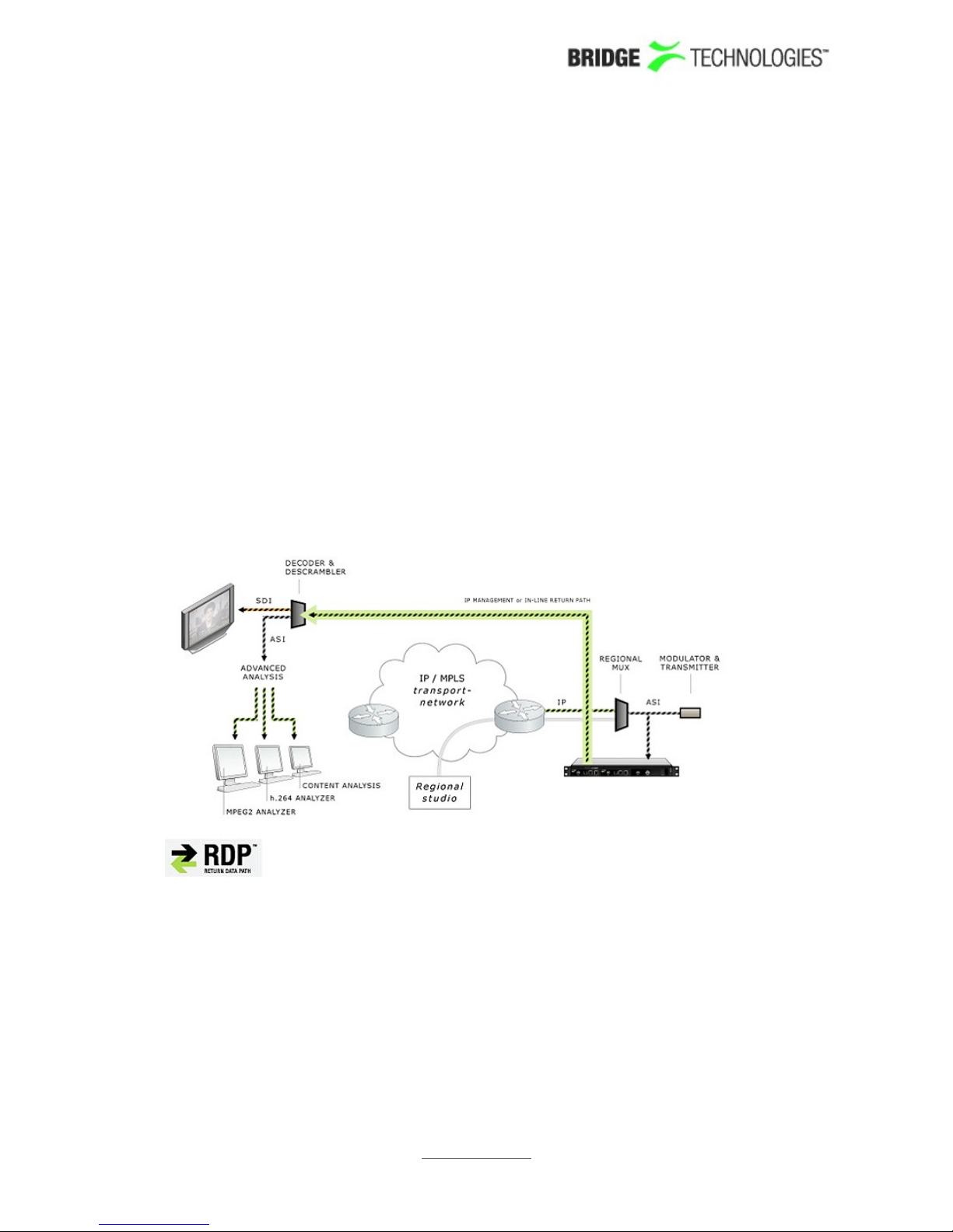
The probe allows the user to define a Return Data Path (RDP), usin the re ular
video/data network or the mana ement network to return a stream. A faulty si nal can
then be further analysed at the studio premises, when necessary.
The recordin functionality allows the user to record a stream, either tri ered
manually by the user or tri ered by a user defined alarm.
Full Service Monitorin (FSM) checks that vital system components like CA-servers are
active.
Optional Ethernet TR 290 monitorin allows the operator to check parameters like
transport stream sync and PSI/SI standards conformity. This option also performs
further PSI/SI analysis, makin it possible to view PSI/SI contents. PID and service
bitrates are also continuously measured.
Optional OTT monitorin allows the operator to set up active testin of Over-the-top
type si nals as found in adaptive bitrate streamin architectures. Formats supported
include Apple (tm) HLS, Microsoft (tm) Smoothstream, MPEG DASH and Adobe (tm)
PROBE USERS' MANUAL VERSION 5.0
2014 © BRIDGE Technolo ies Co AS - Bentsebru ata 20 - N-0476 Oslo, Norway - tel: +47 22 38 51 00 -
www.brid etech.tv
9

HDS.
The probe can be expanded throu h licence options to monitor the T2MI protocol layer
as found in DVB-T2 networks.
The probe can also be licensed with an SCTE 35 option that allows monitorin and
lo in of splice time codes embedded in the transport streams.
1.2 How to use this manual
This users' manual is valid for software versions 5.0 of the probe.
Throu hout this manual the term stream is often used rather than unicast or multicast.
One stream may consist of one or more services, and refers to one IP uni- or multicast
(for Ethernet input) or one transport stream (ASI, COFDM, QAM/VSB or QPSK/DVB-S2).
Chapter 3 lists safety precautions, and this chapter should be read prior to equipment
installation.
Chapter 4 explains how to install the equipment in a rack, and also how to perform the
necessary initial confi uration of the probe mana ement IP-address. A step-by-step
quick installation uide is found in section 4.1.
Chapter 5 contains a quick setup uide; a step-by-step description of how to setup a
probe once the initial setup has been performed.
Chapter 6 describes the raphical user interface (GUI) as seen when pointin a web
browser to the probe's IP-address.
Appendix I describes the alarm handlin in the probe versus the VideoBrid e
Controller (VBC).
Appendix II explains some useful Ethernet monitorin practices.
Appendix III explains the OTT profile health bar and timeline.
Appendix IV explains a probe software upload procedure used when up radin from
software versions older than 4.2.
Note that current versions of the users' manual can be found on the
http://www.brid etech.tv website. Lo -in as end user: cu tomer with password:
xma 4u . Additional technical documentation is also found at the same location.
PROBE USERS' MANUAL VERSION 5.0
2014 © BRIDGE Technolo ies Co AS - Bentsebru ata 20 - N-0476 Oslo, Norway - tel: +47 22 38 51 00 -
www.brid etech.tv
10

2 PRINCIPLE OF OPERATION
The probe module is equipped with two Ethernet ports and an SFP optical port. The
user selects which transport stream si nal input to be used by the monitorin en ine,
either the Ethernet video/data port or the SFP optical input. Mana ement of the probe
is conducted via the Ethernet mana ement port or alternatively in-band via the
Ethernet video/data port.
Fi ure 1: The Probe Module
PROBE USERS' MANUAL VERSION 5.0
2014 © BRIDGE Technolo ies Co AS - Bentsebru ata 20 - N-0476 Oslo, Norway - tel: +47 22 38 51 00 -
www.brid etech.tv
11
Autres manuels pour VB20
1
Ce manuel convient aux modèles suivants
1
Table des matières
Autres manuels BridgeTech Instrument de mesure
Manuels Instrument de mesure populaires d'autres marques

Endress+Hauser
Endress+Hauser Proline Promag 50 Caractéristiques techniques

Siemens
Siemens SITRANS F Coriolis FCT030 Manuel de la liste des pièces

KLINGER
KLINGER CMF V Series Manuel utilisateur

EXFO
EXFO FTB-2 Manuel d'exploitation et d'entretien

Keysight
Keysight M8290A Manuel utilisateur

ADTEK
ADTEK MW-5 Manuel utilisateur