Brava G 4/5 108 Manuel utilisateur

1
Betriebsanleitung
Operating Instructions
Dampflokomotive G4/5 108
Basierend auf einem Entwurf für die abessinische Bahn entwickelte
die SLM in Winterthur eine vierfach gekuppelte Schlepptenderlok für
die Rhätische Bahn. Die ersten vier Lokomotiven der Serie G 4/5
wurden 1904 an die RhB abgeliefert. Die Konstruktion war ein voller
Erfolg, bis 1915 wurden insgesamt 29 Lokomotiven in Dienst gestellt.
Die einsetzende Elektrifizierung der Rhätischen Bahn beendete dann
die Lieferung von Dampfloks. Zahlreiche Loks wurden ins Ausland
verkauft, zwei Lokomotiven jedoch verblieben bei der Rhätischen
Bahn. Sie werden zur Freude der Eisenbahnfans bei Sonderfahrten
eingesetzt.
Steam locomotive G 4/5 108
Based on a design for the Abyssinian Railway, the SLM in Winterthur
developed a four-coupled tender locomotive for the Rhätische Bahn.
The first four locomotives in the G 4/5 series were delivered to the
Rhätische Bahn in 1904. The design was a resounding success and a
total of 29 locomotives had been put into service by 1915. The onset
of electrification at the Rhätische Bahn then put a stop to further
deliveries of steam locomotives. Numerous locomotives were sold
overseas, though two remained with the Rhätische Bahn. Railway
fans are delighted that they are still used for excursions.
G4_5_10000_10001.p65 29.09.2005, 14:401

2
Benennung Seite
Allgemeine Montage- und Sicherheitshinweise ................................. 4
Das Modell – technische Merkmale ................................................... 4
Hinweis zum Betrieb ........................................................................... 4
Lokkupplung vorne .............................................................................. 4
Arbeiten vor der Inbetriebnahme
• Entnahme der Lok aus der Verpackung ......................................... 6
• Zusatzbauteile montieren ............................................................... 7
• Lautstärkenregelung / Auspuffschläge ........................................... 7
Wartungsarbeiten
Lokomotive
• 1. Ölen ........................................................................................ 10
• 2. Tenderkupplung...................................................................... 10
• 3. Lok-Tenderkupplung tauschen .............................................. 11
• 4. Rauchgenerator tauschen / Rauchöl einfüllen ...................... 11
• 5. Rauchgenerator Vakuumbremse montieren / befüllen .......... 11
• 6. Pufferbohlenblende der Lokomotive montieren ..................... 11
• 7. Schaltmagnet montieren ....................................................... 11
• 8. Gehäuse demontieren ............................................................ 11
• 9. Motor tauschen...................................................................... 11
• 10. Platine Kessel tauschen ......................................................... 11
• 11. Beleuchtungseinrichtung ....................................................... 12
• 12. Wartungsarbeiten an Radsätzen, Getriebe,
Deichsel und Kuppelgestänge ............................................... 12
• 13. Schleifkohlen wechseln ......................................................... 12
Tender
• 1. Gehäuse demontieren ............................................................ 14
• 2. Platine tauschen .................................................................... 14
• 3. Verbindungskabel tauschen ................................................... 14
• 4. Wartungsarbeiten an Radsätze .............................................. 14
• 5. Digitaldecoder / Soundmodul tauschen ................................ 14
• 6. Digitalisieren / Soundnachrüstung ......................................... 14
• 7. Stromabnehmer tauschen ..................................................... 15
• 8. Schalter Tenderunterseite ...................................................... 15
• 9. Schalter auf der Platine ......................................................... 16
Ersatzteilliste ..................................................................................... 26
Bestellhinweis
• Bestellbeispiel ............................................................................... 35
Inhaltsverzeichnis
G4_5_10000_10001.p65 29.09.2005, 14:402

3
Description Page
General assembly and safety information ........................................... 5
The model – technical features ......................................................... 5
Instructions for operation .................................................................... 5
Locomotive coupling at the front ....................................................... 5
Work to be performed before starting up
• Removing the locomotive from the packaging .............................. 8
• Fitting additional parts .................................................................... 9
• Sound control / exhaust puffs ........................................................ 9
Maintenance work
Locomotive
• 1. Lubrication ............................................................................. 18
• 2. Tender coupling ...................................................................... 18
• 3. Replacing the loco-tender coupling ...................................... 19
• 4. Replacing the smoke generator / filling with smoke oil ........ 19
• 5. Mounting / filling the smoke generator vacuum brake ......... 19
• 6. Fitting the locomotive buffer cover ........................................ 19
• 7. Fitting the switching magnet ................................................. 19
• 8. Dismantling the housing ........................................................ 19
• 9. Replacing the motor .............................................................. 19
• 10. Replacing the boiler PCB ....................................................... 19
• 11. Lighting system ...................................................................... 20
• 12. Maintenance work to the wheelsets, gear,
drawbar and coupling rod ...................................................... 20
• 13. Replace carbon contacts....................................................... 20
Tender
• 1. Dismantle housing .................................................................. 22
• 2. Replace PCB .......................................................................... 22
• 3. Replace connection lead ....................................................... 22
• 4. Maintenance work to the wheelsets ..................................... 22
• 5. Replacing the digital decoder / sound module ...................... 22
• 6. Digitisation / sound upgrading ............................................... 22
• 7. Replacing the pick-up ........................................................... 23
• 8. Switches, bottom of the tender ............................................ 23
• 9. Switch on the PCB ................................................................ 24
Spare parts list .................................................................................. 26
Order notice
• Order example .............................................................................. 35
Contents
G4_5_10000_10001.p65 29.09.2005, 14:403

4
Allgemeine Montage- und Sicherheitshinweise
• Diese Bedienungsanleitung beschreibt sämtliche Arbeitsvorgänge,
die zur Wartung und Instandhaltung notwendig sind.
Bitte lesen Sie diese Bedienungsanleitung bevor Sie mit den
Arbeiten beginnen.
• Bei unsachgemäßem Umgang mit elektrischen Bauteilen können
diese zerstört werden. Für entsprechende Arbeiten (z.B. Platinen-
wechsel) können Sie sich an Ihren Fachhändler oder den Hersteller
wenden.
• Bei den folgenden Wartungsarbeiten ist die jeweilige Demontage
beschrieben, der Zusammenbau ist in umgekehrter Reihenfolge
auszuführen.
• Achten Sie beim Zerlegen der Lokomotive auf die Einbaulage der
entsprechenden Bauteile. Wird ein Bauteil falsch eingebaut kann
dieses zerstört werden oder es kommt zu Funktionsstörungen im
Betrieb.
Das Modell – technische Merkmale
Decoder (je nach Ausführung optional)
– Adressbereich 1-9999
– NMRA-konform
– ruhiger Motorlauf durch Motoransteuerung über 18 kHz
– 14, 27, 28, 128 Fahrstufen je nach Datenformat
– lastgeregelt
– vorbildgetreue Schweizer Signalisierung der Lok incl. Rangierlicht
(3+3)
– Schlusslicht einzeln schaltbar für Schubbetrieb
Sound
– Dampfausstoß synchron zur Raddrehung
– wahlweise 2 oder 4 Auspuffschläge
– lastabhängiges Dampfgeräusch
– Umschaltung des Soundmoduls auf „Fahren ohne Zug“
– Zylinderentwässerung schaltbar
– Schaffnerpfiff und Bahnhofsansage schaltbar
– Pfeife schaltbar mit variabler Dauer
– Luftpumpe
– Bremsgeräusch
– Flackerlichtansteuerung in Abhängigkeit vom Sound „Kohle-
schaufeln“
– Ansteuerung des Dampferzeugers für die Vakuumbremse
Hinweis zum Betrieb
Beim Betrieb auf engen Radien benötigt die Lok ein sehr großes
Lichtraumprofil. Bitte überprüfen Sie Ihre Anlage in Bezug auf
Hindernisse wie Bahnsteigkanten, Brückengeländer oder Tunnel-
portale. Enge Radien sind aufgrund der Betriebssicherheit zu
vermeiden.
Lokkupplung vorne
Das Modell ist vorne (bedingt durch den großen Überhang in engen
Radien) nur auf großen Radien kuppelbar.
G4_5_10000_10001.p65 29.09.2005, 14:404

5
General assembly and safety information
• These operating instructions describe all work steps necessary for
maintenance and repair. Please read these operating instructions
carefully before you start with your work.
• In the case of incorrect handling of electrical components, they
may be destroyed. Please ask your specialist dealer to help with
the necessary work (e.g. changing circuit boards).
• In the case of maintenance work, the disassembly is described
below, to re-assemble the tractor reverse the work steps.
• When dismantling the locomotive make a note of the mounted
position of the individual parts. An incorrectly mounted part can
be destroyed or operation can be disrupted.
The model – technical features
Decoder (optional depending on version)
– Address range 1-9999
– Complies with NMRA
– Quiet motor running with 18 kHz motor control
– 14, 27, 28, 148 stages depending on data format
– load-controlled
– Swiss loco signalling true to the original including shunting light
(3+3)
– Rear light can be switched individually for thrust operation
Sound
– Steam puffs synchronous with the wheels turning
– Optionally 2 or 4 exhaust puffs
– Load-dependent steam noise
– Sound module changeover to "moving without train"
– Cylinder drainage can be switched on
– Guard whistle and station announcement can be switched on
– Whistle can be switched on with variable duration
– Air pump
– Braking noise
– Flickering light control depending on "coal shovel" sound
– Steam generator controlled for vacuum brake
Operating instructions
The locomotive needs a very large space profile when operating
round narrow radii. Please check your system with regard to
hindrances such as platform edges, bridge rails or tunnel entrances.
Narrow radii should be avoided in the interests of operating safety.
Locomotive coupling at the front
The model can only be coupled to large radii at the front (because of
the large overhang in narrow radii).
G4_5_10000_10001.p65 29.09.2005, 14:405
6
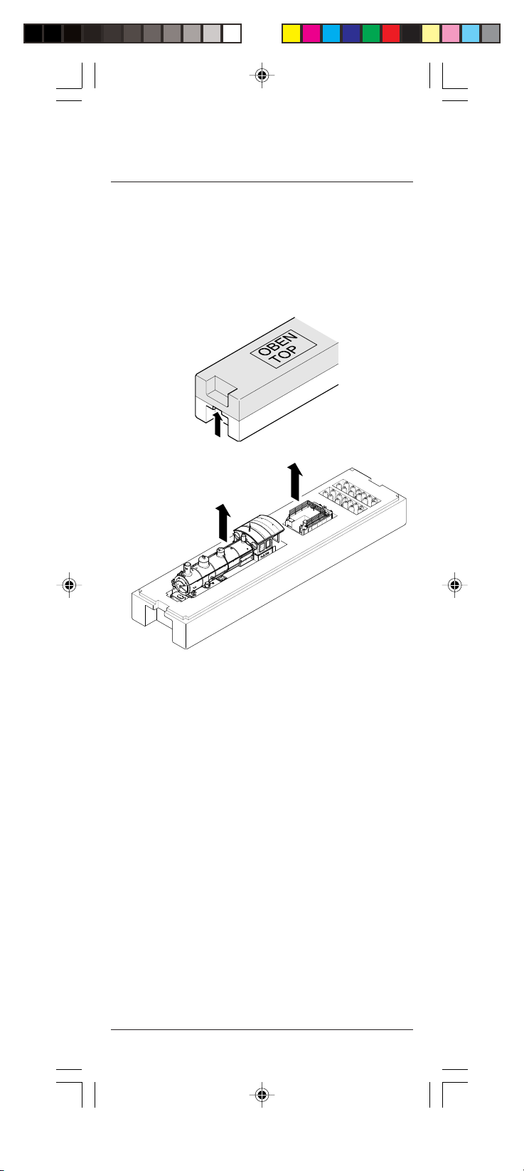
Entnahme der Lok aus der Verpackung (Fig. 1)
Verschluß der Verpackung öffnen. Schutzverpackung
mit Lok entnehmen und auf einen Tisch oder ähnliches abstellen.
Achtung: Darauf achten, dass die Beschriftung „Oben“ auf der
Schutzverpackung von oben lesbar ist.
Deckel nach oben abnehmen, Lok bzw. Tender entnehmen.
Arbeiten vor der Inbetriebnahme
Fig. 1
G4_5_10000_10001.p65 29.09.2005, 14:406

7
Zusatzbauteile montieren (Fig. 2)
In der Verpackung sind folgende Bauteile beigelegt.
• 1 = 3 x Deichsel, Montage siehe Seite 11, Punkt 3.
• 2 = 3 x Werkzeug
• 3 = 1 x Pufferbohlenblende
• 4 = 1 x Metallplatte
Lautstärkeregelung / Auspuffschläge (Fig. 3)
(nur in Verbindung mit Soundmodul)
Hinter der Kesseltüre (3) befindet sich das Potentiometer (1) für die
Lautstärkeregelung des Lautsprechers und der Schalter (2) für 2 oder
4 Auspuffschläge.
Drehen des Potentiometers (1) im Uhrzeigersinn erhöht die Lautstär-
ke. Der Schalter (2) hat zwei Stellungen. Wie in der Grafik dargestellt
von vorne gesehen, linke Stellung 2 Auspuffschläge, rechte Stellung
4 Auspuffschläge.
12 3
Fig. 3
21
3
4
Fig. 2
G4_5_10000_10001.p65 29.09.2005, 14:407

8
Work to be performed before starting up
Removing the locomotive from the packaging (Fig. 1)
Open the packaging seal. Take the protective packaging with the
locomotive out of the box and place it on a table or similar.
Caution: Make sure that the wording "TOP" is legible on the top of
the protective packaging. Lift the top off and remove the locomotive
and tender.
Fig. 1
G4_5_10000_10001.p65 29.09.2005, 14:408

9
Fitting additional parts (Fig. 2)
Accessory parts have been loosely enclosed in the packaging.
• 1 = 3 x Draw bar, mounting see page 19, item 3.
• 2 = 3 x Tools
• 3 = 1 x Buffer detail
• 4 = 1 x Metal plate
Sound control / exhaust puffs (Fig. 3)
(only together with the sound module)
The potentiometer (1) for adjusting the sound control of the
loudspeaker and the switch (2) for 2 or 4 exhaust puffs is located
behind the boiler door (3).
Turn the potentiometer (1) clockwise to increase the volume. Switch
(2) has two positions. As shown in the graphic at the front, setting on
the left for 2 exhaust puffs, setting on the right for 4 exhaust puffs.
12 3
Fig. 3
21
3
4
Fig. 2
G4_5_10000_10001.p65 29.09.2005, 14:409

10
Wartungsarbeiten an der Lok
1. Ölen (Fig. 4)
Der Motor und die Lagerstellen der Radsätze sollten an den
gekennzeichneten Punkten sparsam mit Öl der Modellbaubranche
geölt werden. Zum Ölen des Motors ist das Gehäuse abzunehmen,
siehe Seite 11, Punkt 8.
Fig.4
Motor
Räder
2. Tenderkupplung (Fig. 5)
Für einen geringeren Pufferabstand zwischen dem Tender und den
angehängten Wagen kann man die Tenderkupplung an zwei Punkten
mittels einer Schraube fixieren. Befestigungspunkt (1) ist für Betrieb
auf kleinen Radien und Befestigungspunkt (2) für Betrieb auf großen
Radien vorgesehen.
Fig. 5
2
1
G4_5_10000_10001.p65 29.09.2005, 14:4010
Table des matières
Langues :
Autres manuels Brava Jouet


