Bodet Profil 730 Manuel utilisateur

1
Profil 730 - Profil 740
WI-FI NTP Receiver
Réceptrice NTP WIFI
Installation and operation manual
Manuel d’installation et de mise en service
ANALOGUE CLOCKS
HORLOGES ANALOGIQUES
When receiving goods please check nothing is broken otherwise make a claim near shipping company.
S’assurer à réception que le produit n’a pas été endommagé durant le transport pour réserve au transporteur.
BODET Time&Sport
1 rue du Général de Gaulle
49340 TREMENTINES I France
Tel. support France: 02 41 71 72 99
Tel. support export: +33 241 71 72 33
Ref : 608612A
www.bodet-time.com

2
EN
Table of contents
Safety information 4
1. Initial checks 5
1.1 Unpacking the clock 5
1.2 Cleaning the clock 5
1.3 Pre-requisites 5
1.4 Safety instructions – Precautions for use 6
2. Installation 7
2.1 Mechanical installation 7
2.1.1 Wall mounting with screws 7
2.1.2 Wall installation with locking disc 7
2.1.3 Installation on double-sided mounting 7
2.2 Electrical installation 8
2.2.1 Low voltage power supply 8
2.2.2 100-240V Power Supply 10
3. Configuring Wi-Fi clocks 11
3.1 Manual Configuration 11
4. Web Server Description 14
4.1 Home page 14
4.2 Wi-Fi configuration page 15
4.3 Network configuration page 17
4.4 Time Setup/Synchronisation page 18
4.5 Alarm configuration page 20
4.6 System page 22
5. Help with settings 23
5.1 Mechanical set-up 23
5.1.1 Using a shunt 23
5.1.2 LED status 23
5.2 Default configuration 25
6. Technical features 26
6.1 Dimensions 26
6.2 Data 27
7. What to do if… ? Check. 28
8. Appendix 29
8.1 Changing time according to the time zone 29

3
FR
Table des matières
Informations relatives à la sécurité 30
1. Vérification initiale 31
1.1 Déballage de l'horloge 31
1.2 Nettoyage de l'horloge 31
1.3 Pré-requis 31
1.4 Consignes de sécurité - précaution d’utilisation 32
2. Installation 33
2.1 Installation Mécanique 33
2.1.1 Installation murale par vis 33
2.1.2 Installation murale par disque de verrouillage 33
2.1.3 Installation sur support double face 33
2.2 Installation électrique 34
2.2.1 Alimentation TBT 34
2.2.2 Alimentation 100-240V 36
3. Configuration des horloges Wi-Fi 37
3.1 Configuration manuelle 37
4. Description du Serveur Web 40
4.1 Page Accueil 40
4.2 Page Configuration WIFI 41
4.3 Page Configuration réseau 43
4.4 Page Configuration de l'heure / synchronisation 44
4.5 Page Configuration des alarmes 46
4.6 Page Système 48
5. Assistance au paramétrage 49
5.1 Paramétrage mécanique 49
5.1.1 Utilisation du shunt 49
5.1.2 Etat de la Led 49
5.2 Configuration par défaut 51
6. Caractéristiques techniques 52
6.1 Dimensions 52
6.2 Données 53
7. Que faire si... ? Vérifier. 54
8. Annexes 55
8.1 Changement d'heure en fonction du fuseau horaire 55

4
Safety information
The following icons are used to indicate risks or sources of danger when installing, using and maintaining this product.
Symbol Description
IEC60417 - 1641
Operating instructions
IEC60417 - 5002
Positioning of cell
IEC60417 - 5017
Earth, ground
IEC60417 - 5018
Functional earthing
IEC60417 - 5019
Protective earth (ground)
IEC60417 - 5031
Direct current
IEC60417 - 5032
Alternating current
IEC60417 - 5033
Both direct and alternating current
IEC60417 - 5036
Dangerous voltage
IEC60417 - 5172
Class II equipment
IEC60417 - 6040
Caution, ultraviolet radiation
IEC60417 - 6041
Caution, visible radiation
IEC60417 - 6042
Caution, risk of electric shock
IEC60417 - 6092
Class II equipment with functional earthing
IEC60417 - 6151
Caution, infrared radiation
IEC60417 - 6172
Disconnection, all power plugs
IEC60417 - 6414
Waste Electrical and Electronic Equipment (WEEE)
IEC60417 - 0434b
Caution
IEC60417 - 5032-1
Three-phase alternating current
IEC60417 - 5032-2
Three-phase alternating current with neutral conductor
IEC60417 - 5009
Power, Stand-by
IEC60417 - 6069
Caution, very bright light
EN

5
1. Initial checks
Thank you for choosing a BODET clock.
This product has been carefully designed to ensure your satisfaction, adhering to quality
processes ISO9001 and ISO14001.
We recommend that you read this manual and the general safety measures and operating
instructions carefully before handling the clock.
Keep this manual for reference for the lifespan of your clock so that you can refer to it when
necessary.
Data not contractual. Bodet reserves the right to make certain
functional, technical and aesthetic changes to the devices without prior notice.
Failure to observe these instructions may cause irreversible damage and invalidate the
warranty.
In this case, Bodet cannot be held liable.
These instructions relate to the "NTP Wi-Fi" models.
For other models, please refer to the corresponding instructions.
1.1 Unpacking the clock
Carefully unpack the clock and check the contents of the package. These should include :
– the clock (with a label showing the product's MAC address) and this manual.
– a screw with a wall pin.
Note: On the back of the movement, a label species the default conguration of the clock.
1.2 Cleaning the clock
Use an anti-static product. Never use alcohol, acetone or other solvents,
which may damage the clock's casing or glass.
1.3 Pre-requisites
To put the clocks into service, install the BODET Detect software on a laptop or BODET Detect
Mobile from the Google Play Store (QR code) if you have an Android smartphone.
This software is available to download for free on the Bodet website at www.bodet-time.com.
EN

6
1.4 Safety instructions – Precautions for use
Read the safety instructions carefully before installing and conguring the clocks.
Observe the safety tips at all times during installation, use and maintenance of the product.
Key to symbols:
: indicates advice, a recommendation or other practical information,
: indicates that special attention needs to be paid.
: indicates that misuse or failure to follow the instructions could result in an electrical hazard.
This information must be taken into account when installing or using the clock.
Installing the product
Installation and maintenance of this device must be carried out by qualied personnel.
The electrical installation of this equipment must comply with the rules laid down in the
standards in force in the country where the product is used.
Opening the product
There are no user-serviceable components in this product.
Contact BODET customer service if the product needs to be repaired.
Never open the product while it is connected to a power source.
Before working on the product, switch o the upstream power supply
(circuit breaker, etc.).
Grounding
This product is a class 2 productand therefore does not require grounding.
EN
7
2. Installation
Select a location to install the clock, preferably away from sources of electrical interference, such
as transformers.
2.1 Mechanical installation
2.1.1 Wall mounting with screws
These clocks are simply hung on a screw head:
1/ Install a 4 mm-diameter screw at the desired height, with the head protruding by 3 mm,
2/ Carry out the wiring according to the type of clock and power supply (see chapter 2.2),
3/ Install the clock in place.
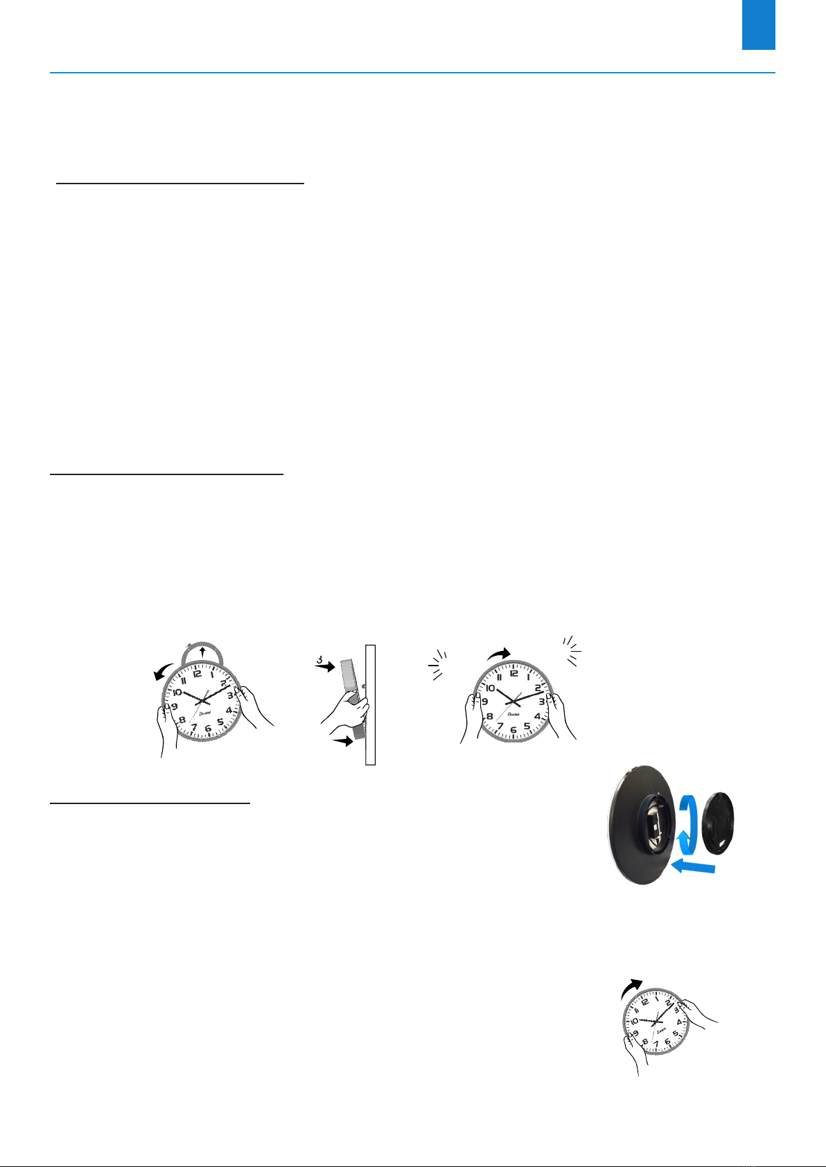
2.1.2 Wall installation with locking disc
Thin wall bracket (ref: 981 003):
1/
Fix this bracket with four 6 mm-diameter screws after passing the wiring inside the disc
,
2/ Carry out the wiring according to the type of clock and power supply (see chapter 2.2),
3/ Place the clock on the bracket (12 o'clock must be tilted to the left) and turn it clockwise to bring
the clock into its nal position.
3
2
1
2
4
Clic Clac
Wall bracket (ref: 981 006):
Place the disc on the back of the clock and turn clockwise to lock the
bracket.
The opening for the cables should be downwards.
2.1.3 Installation on double-sided mounting
1/ Fix the double-sided bracket to the wall or ceiling with two
6 mm-diameter screws,
2/ Carry out the wiring according to the type of clock and power supply
(see chapter 2.2),
3/ Place the clocks on the bracket (12 o'clock should be tilted to the left)
and turn them clockwise to bring them into their nal positions.
EN

8
2.2 Electrical installation
The wiring is dierent depending on the type of clock (single or double sided) and the type of
power supply (low voltage or 100-240V )
2.2.1 Low voltage power supply
Single-sided model:
POWER SUPPLY
6-24 V
+-
- Strip the cable from the wall over 10 mm,
- Strip the two wires with a cross-section of 1.5 mm² (maximum) over 5 mm,
- Connect the wires directly to the terminal block on the back of the clock
(at the bottom of the movement) in the power supply terminals, 6-24 V ,
respecting the + / - polarity indicated on the label,
- Ax a cable retainer around the power supply wires.
1 cm
Remember, conductors on the same circuit must be attached to each
other close to the terminal block to avoid reduced isolation should
one of the terminals become loose.
Double-sided model:
- Route the wiring through the bracket arm,
- Wire the rst clock Aas a single-sided clock (see above),
- Wire the second clock Bby making a cascade connection to the + / - power supply, 6-24 V
terminals of the rst clock A.
A B
EN

9
For clocks with a low-voltage power supply (single and double-sided),
observe the recommended wiring distances for the installation.
It is compulsary, for a correct running, to respect the following parameters.
These parameters are calculated considering 8/10 mm wire section.
Distance
(m)
Number of clocks Number of
clocks
Distance (m)
24 V 12V 24 V 12V
100 12 4 1 1250 375
200 6 2 10 125 37
300 4 1 20 62 20
400 3 1
600 2 0
1000 1 0
EN

10
2.2.2 100-240V Power Supply
Single-sided model:
Contact surface of the jacket/connector for insulation
Female Connector Socket
- Strip the cable from the wall over 10 mm,
- Strip the two wires with a cross-section of 1.5 mm²
(maximum) over 5 mm,
- Position the cable and wires inside the female plug
of the supplied connector, checking:
• that the cable jacket penetrates the connector
suciently to ensure proper insulation,
(see image opposite),
• the direction of connection of the wires (phase and neutral),
- Screw the two screws onto each of the two wires to hold them in position,
- Connect the newly formed female plug to the male connector
1
in the clock at the top right of the
movement.
Power supply (ref: 982 001).
Note: The Prol 740
backlit clock is equipped with a
dierent power supply.
The connection is done in a
similar way.
1
For the double-sided model:
- Route the wiring through the bracket arm,
- Wire the rst clock Aas a single-sided clock (see above),
- Wire the second clock Bby making a cascade connection to the + / - power supply, 6-24 V
terminals of the rst clock A.
A B
For a double-sided Prol 740 clock model with lighting or for a double-sided Prol 730
/ 740 model with two clocks, each with a power supply, you must split the mains cable
(with a split tting) to then wire each of the two clocks like a single-sided clock.
The procedure is similar if there are two mains cables: connect each clock as a
single-sided clock.
EN
Autres manuels pour Profil 730
3
Ce manuel convient aux modèles suivants
1
Table des matières
Langues :
Manuels Horloge de pointage populaires d'autres marques


Funtronix
Funtronix SCORE-N-TIME T-240 Manuel utilisateur

IKEA
IKEA NUFFRA 10357872 Manuel utilisateur

Multipipe
Multipipe 22-23015 Guide de l'utilisateur

L’EPEE 1839
L’EPEE 1839 SUN CLOCK Manuel utilisateur

Oregon Scientific
Oregon Scientific TW331 Manuel utilisateur

MT Logic
MT Logic CL-471 Manuel utilisateur

Easy Clocking
Easy Clocking XENIO 500 Manuel

Amano
Amano MTX-15 Manuel utilisateur

LA CROSSE CLOCK
LA CROSSE CLOCK Harper 404-3450A Manuel utilisateur

Europa components
Europa components ET167DYD Manuel utilisateur

TONIN CASA
TONIN CASA Opaca circle Manuel utilisateur

CS TIMECLOCK
CS TIMECLOCK 2110 Manuel d'instructions